

A new kind of sensor has been developed for level measurement, based on the guided radar (TDR) principle. It can be used for pressures up to 400 bar (40 MPa) and for temperatures ranging from -200°C to +400°C. The sensor uses a single-rod wave guide (Goubau wave guide) that is insensitive to caking.
The sensor is sealed by means of three redundant seals arranged one after the other without any cavities. As a result, the sensor continues to function even if the primary seal fails. Maximum corrosion resistance is achieved by using materials such as high-purity aluminium oxide ceramic and graphite. Together with the mechanically robust version, in accordance with the requirements of the Pressure Equipment Directive, this allows the sensor to be used in safety equipment to SIL 2 as per IEC 61511-1.
Introduction
The guided radar, also known as time domain reflectometry (TDR), has been known as a method for measuring level for almost 40 years. Here, high-frequency pulses are guided along a probe serving as a surface wave guide, reflected at the product surface and the level is then determined from the transit time. As the pulses propagate at the velocity of light, this results in very short transit times - a resolution of 1 mm corresponds approximately to a transit time difference of 7 ps. For this reason, the reflected signal is transformed to the audio range with a sampling process to then be digitised and evaluated with a microprocessor.
The advantages of the guided radar are that it is relatively independent of product properties such as density, dielectric constant or conductivity, of process conditions such as turbulent surfaces or foam formation, and of tank properties such as the shape, size or internal tank fittings.
Guided radars were not very widespread in process automation up to the mid-1990s. One reason was certainly the relatively high circuit complexity compared to capacitance level measurement for example. Now, however, energy-saving, powerful microcontrollers are available and the cost of components such as graphic displays and low-noise amplifiers have dropped considerably in the past decade. Consequently, sophisticated evaluation algorithms with comfortable plain text display are possible today, which ensure easy commissioning, and reliable operation. As a result, the demand for such devices has increased significantly and today they are accepted as a standard measuring method.
The sensor presented in this document now answers the area of extreme application conditions for this measuring principle. Up to now, this area has been dominated primarily by displacers, capacitance sensors and differential pressure sensors with their own specific limitations.
Sensor design
Structure
The fact that the TDR sensor is not sensitive to application-specific influences is key to its wide area of application.
This is best achieved with a single-rod sensor where the measuring signal extends much further compared to the other possible sensor geometries (particularly two-rod sensors and coaxial sensors). As a result, in the majority of cases interference echoes do not occur in the event of product build-up on the sensor, the signal is not attenuated to any appreciable degree and the envelope delay time is not increased. A further advantage of the single-rod sensor is that sensors even several meters long do not need a spacer in the measuring area where material could build up or which could be damaged from vibration, temperature stress or corrosion.
Figure 1 shows an axial cross-section through the single-rod sensor. The pressure-bearing sensor housing made of austenitic steel 1.4435 (AISI SS 316L) runs as far as the coaxial compression glass-to-metal seal where the signal is fed in via a flexible coaxial cable and an SMA plug connector. Only high-resistance materials able to withstand temperatures are used beneath the glass-to-metal seal. The dielectric consists of 99,7%-purity aluminium oxide ceramic. Compared to glass, ceramic not only has the advantage that it is more stable but can also be used for contact with the process due to its far better hydrolysis resistance. Graphite packing glands are used as the primary process seal as no known elastomer seal can be used up to 400°C and soldered steel-ceramic compounds are far less resistant. The inner conductor is made of Hastelloy C-22 as this material demonstrates excellent stability with a yield strength at 0,2% offset of 427 MPa at ambient temperature. As a result, a flexural strength of 30 Nm is achieved at the probe rod with an inner conductor diameter of just 10 mm. An O-ring seal made of FFKM is used as the redundant seal. The housing adapter is not pressure-bearing and can therefore be designed with thin walls for effective temperature reduction at the electronics.
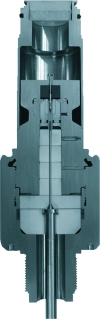
The sealing concept with three redundant seals provides maximum-level safety. Even if the primary process seal fails, the sensor function is maintained without any restrictions as the probe does not have any cavities and thus the high-frequency-specific properties of the probe are not altered by the penetration of fluid. This reduces the probability of undetected dangerous failures, which is important for use in safety equipment to SIL 2 as per IEC 61511-1. The pre-positioned seals serve to protect the gas-tight compression glass-to-metal seal in particular.
Mechanical stability
High pressures constitute a serious hazard potential which is why pressure equipment has to meet specific requirements in most countries. In Europe, the most important is the Pressure Equipment Directive 97/23/EC according to which this sensor is to be classified as a Category I pressure accessory and thus the fundamental requirements of Annex I of the Directive must be met in terms of the device's design. These requirements are substantiated in harmonised standards such as EN 13445 which is used to design this sensor.
Due to the complex geometry of the sensor, it is practically impossible to perform analytical calculations. Rather, the sensor is designed using non-linear finite-element analysis with ANSYS Rev. 7.1 software.
Figure 2 shows the effective stress pattern in the sensor housing at a temperature of 20°C and a process pressure of 400 bar (40 MPa). This also takes into account the stress that occurs from pretensioning the graphite packing glands. Furthermore, it is assumed that the process pressure is also present after the graphite seal, ie, that there is certain leakage of the primary process seal. Comparative results are also obtained for other marginal conditions such as additional tensile or flexural loading or higher temperatures.
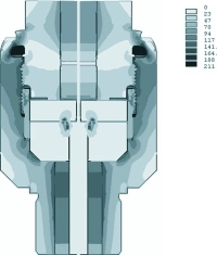
A high degree of strain can be detected in the area of the weld seam between the two parts of the sensor housing. Even though these two parts are connected by a thread, part of the stress affects the weld seam. On the one hand, this is due to the fact that the process pressure radially expands the lower part of the sensor housing, thereby reducing thread flank engagement. On the other hand, there is also axial expansion of the upper part of the sensor housing which also reduces force transfer to the thread. To limit the weld seam strength necessary, and thus not have to use complex welding methods such as electron beam welding, a corrugated contour is machined adjacent to the weld seam whose form and elasticity minimises the stress.
The following applies to a single-rod probe near a metallic container wall:
Where d is the distance to the container wall, b the radius of the probe rod and e the dielectric constant in the area of the probe.
When coupling in air (e >>1) with a probe rod radius of 8 mm, this gives an impedance of 193 Ω for a distance of 100 mm from the wall and 331 Ω for a distance of 1 m from the wall. With the known relations for the reflection factor r and the transmission factor t:
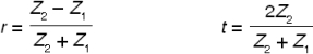
We have -4,6 dB matching for a distance from the wall of 100 mm and -2,6 dB matching for a distance from the wall of 1 m. These relatively poor values are inevitable for a single-rod probe and result in large interference reflection at the transition between the coaxial glass-to-metal seal and the single-rod waveguide.
This can, however, be eliminated by subtracting the echo curve for an empty tank from the echo curve measured and thereby no longer causes any interference. It is only possible to also use the single-rod probe for products with a small dielectric constant with this special evaluation algorithm.
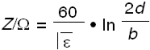
On the other hand, specific measures to be taken with regard to the sensor design are required. Freedom from resonance can be achieved in that only one single jump in impedance occurs within the probe, ie, the complete glass-to-metal-seal is designed with 50 Ω impedance and no multiple reflections can arise as a result. The impedance within the coaxial glass-to-metal-seal is:
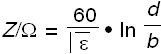
Where d is the diameter of the outer conductor and b is the diameter of the inner conductor. As the diameter of the inner conductor must be at least 10 mm to achieve sufficient bending strength, this would require an outer conductor diameter of 139 mm with aluminium oxide ceramic as the dielectric due to the large e = 10. However, with such a large diameter, other higher-order modes would be able to propagate within the ceramic in addition to the fundamental TEM mode. A high-rate coaxial resonator would result at either side of the glass-to-metal-seal due to the low coupling of these modes which would mean that the goal of freedom from resonance would not be achieved.
For this reason, a smaller outer conductor diameter of 55 mm is selected. Although this only results in an impedance of 32,4 Ω as the length of this mismatched area is intentionally chosen as being very small, no appreciable ringing results.
Application examples
The sensor described here is already in use in numerous applications particularly in the chemical and petrochemical industries and in power stations.
Up to now, displacers have been used very often here. These displacers, however, are very sensitive to product build-up and then display levels that are far too low or are entrained by boiling products and then wear quickly or do not allow any measurement whatsoever.
Compared to capacitance probes, the dielectric constant of the product does not affect the measurement with the guided radar. For example, the dielectric constant of condensate decreases with increasing temperatures, which results in a corresponding measured error during capacitance measurement with fully insulated probes. Figure 3 shows the use of the sensor in such an application.

Pressure sensors are also used for high temperatures. To separate the pressure measuring cell from these temperatures, pulse lines are laid. However, if vacuums occur within the process, these pulse lines can be sucked empty and the change in hydrostatic pressure results in an incorrect display. Due to its stability towards temperatures, the sensor described here can be used directly in the product to be measured with the result that no such problems occur.
For more information contact Sean Frost, Endress+Hauser, +27 (0) 11 262 8000, [email protected]
| Tel: | +27 11 262 8000 |
| Email: | [email protected] |
| www: | www.endress.com |
| Articles: | More information and articles about Endress+Hauser South Africa |


© Technews Publishing (Pty) Ltd | All Rights Reserved
 printer friendly version