

The Westermo On Time industrial managed switch series is available with redundant ring technology. This eliminates network failure caused by fibre or copper failures on the trunk ports (ring ports). The speed of ring recovery is an essential part of designing a network. The Westermo OnTime FRNT (fast re-configuration of network topology) version 0 protocol can recover from a failure in only 20 ms if such a failure does occur. When used in conjunction with redundant power supplies a very reliable system can be designed.
Standard Ethernet networks would collapse and fail if normal office-based Ethernet switches were formed into a complete ring. This failure is commonly referred to as a 'broadcast storm' as Ethernet Packets have multiple routes on a network to communicate to devices. Usually, an incorrect type of packet broadcasts (or floods) over a network and causes hosts to respond all at once, typically with wrong responses. This starts the process over and over again; hence the network crashes.
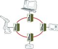
The FRNT0 is similar to the IEEE Spanning Tree Protocol (STP) except for the following: each switch in a ring topology has knowledge of the network topology, see Figure 1, ie, not only to its neighbouring switches as is the case for STP.
Event-based principle
An FRNT topology change event packet will be sent directly to the focal point switch in case of a topology change (eg, a link loss or a link establishment), while a STP implementation will only send STP control packets one network hop. The focal point switch will, based on the received topology change event packet from the topology change detecting switches, generate a topology change command. This packet is sent to each member switch in the ring. The time it takes from the occurrence of a topology change until the corresponding topology change event packet is received on the focal point is typically a fraction of a ms or a few ms at the most, even though the number of the switches in the ring is high.
200 switches in a ring
The FRNT0 concept contains in principle no limitation for the maximum number of FRNT0 enabled switches that can be installed in a single ring. The maximum number has been set to 200 switches.
20 ms re-configuration time
A large number of switches in a ring have only a small impact on the re-configuration time of the network topology. Example: 100 switches on the path between the topology change detecting switch and the focal point with a very high network load on the links (eg, 50% of full wire speed).
The switch latency in the no load scenario is 15 microseconds (µs), while a conservative estimate in case of 50% load is 70 microseconds (µs). This gives 3 ms round trip propagation delay in a no load scenario and 14 ms round trip propagation delay in the (conservative) high load scenario.
The most time consuming part in case of a topology change is MAC table update procedure. The MAC tables on each switch must be updated in case of a topology change. This operation takes approximately 10 ms. This gives a re-configuration time of approximately 20 ms.
Connection oriented protocol
The member to focal point communication is based on a connection oriented protocol. This means that the protocol will handle packet loss of FRNT control packets. Packet loss is very unlikely in a normal scenario due to the excellent bit error rate (BER) properties of wired Ethernet (copper or fibre), ie, BER should be better than 10-11. However, one must be able to handle a situation where a trunk link might suffer from poor BER with packet loss as a result. This connection oriented protocol is very fast. An FRNT control packet, generated by the member, will be re-sent after 30 ms if no acknowledgement is received from the focal point.
Full immunity vs any type of network load
The loss of FRNT packets due to a network overload situation is not an issue for the FRNT0 control protocol. Thus, any unicast-, multicast- or broadcast network load can be generated on the network without any FRNT0 packet loss. An overload situation in this context means that the interface to the switch CPU is a network bottleneck, ie, important control packets must compete vs other packet to the CPU. Broadcast load is for all practical purposes the most critical network load in this context. The FRNT0 protocol is, however, protected against such an overload scenario due to the following properties:
* Broadcast bandwidth limitation.
* Unique VLAN configuration for the FRNT control packets.
* FRNT packets defined as packet with highest possible QoS level.
Similar proprietary network redundant protocols from other vendors are in most cases based on polling instead of event controlled handling of a topology change. This will introduce a slower establishment of a new topology. The FRNT0 protocol is also based on polling as a supplementary function to the event-based part of the protocol. This function has only relevance in case of a multiple point of failure (single point of failure is handled by the of event controlled handling of a topology change).
Link qualification based on data link layer protocol, LHP
A major problem with most network redundancy protocols is the probability for having a network loop where a potential storm can be generated only in one direction (not both directions), and where this is not detected by the root (master) switch. This problem can only be handled if the switches support a link layer protocol that is used in order to qualify a link. The FRNT0 protocol has support for such a protocol. This Westermo OnTime protocol is referred to as the Link Health Protocol (LHP). The LHP makes sure that packets can be both sent and received on a trunk port before the link is properly qualified. This protocol is mandatory if the trunk ports are based on fibre.
FRNT0 main properties
* Event-based principle.
* 200 switches in a ring.
* 20 ms re-configuration time.
* Connection oriented protocol.
*p Full immunity vs any type of network load (uni- multi- and broadcast).
* Link qualification based on data link layer protocol, LHP.
For more information contact Throughput Technologies, 011 705 2497, [email protected]
| Tel: | +27 11 705 2497 |
| Email: | [email protected] |
| www: | www.throughput.co.za |
| Articles: | More information and articles about Throughput Technologies |


© Technews Publishing (Pty) Ltd | All Rights Reserved
 printer friendly version