
As it is with all matters technical, it is important that all involved are familiar with the terms used in any discussion or enquiry. This article looks at the data it is customary to quote in technical descriptions of pressure sensors, pressure transducers and pressure measuring converters, with a view to familiarising the reader with what is meant by terms that are used.
Measuring range/measuring span
The measuring range is the span between the start and the end of the measurements. The error limits quoted in the data sheet apply within this measuring range. The type of pressure, eg positive relative pressure (overpressure), negative relative pressure (underpressure), absolute pressure or pressure difference, is also specified in order to define the measuring scope.
Overload range
The overload range defines the pressures to which a pressure-measuring converter can be exposed without it suffering permanent damage, eg zero-point offset. The pressure-measuring converter is allowed to deviate from its specified technical data in this span between the measuring range and overload limit. The overload limit is usually defined by the sensor's principle of operation.
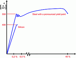
With piezoresistive pressure measuring converters the overload pressure is identical with bursting pressure. In the case of thin-film pressure measuring converters, on the other hand, there are notable differences between overload pressure and bursting pressure. This is owing to the sensor materials silicon and stainless steel. While steels enter a flow phase when they exceed their resilient range, brittle materials display a linear characteristic up to bursting point.
Bursting pressure
Bursting pressure defines the pressure range which, if exceeded, can lead to the total destruction of the pressure measuring converter and hence to a loss of process medium.
Auxiliary energy
An auxiliary energy supply is required to operate pressure transducers and pressure measuring converters. The most widespread solution is a direct voltage of 24 V. Thanks to the use of voltage-stabilising components, pressure-measuring converters usually have a bigger supply voltage range of eg 10 to 30 V d.c. Within this range any supply voltage variation has no effect on pressure readings. For example, if the pressure measuring converter is calibrated in the factory with an auxiliary voltage of 24 V d.c. there should be no change of accuracy if the converter is actually operated with just 12 V d.c. The effects of supply voltage variations should not greatly exceed 0,1% per 10 V.
Output signal (analog, digital)
Current and voltage signals have become established as the main alternatives for output signals. Exactly which output signal is selected will depend mainly on the indicating and control devices, which follow on after the pressure-measuring converter. As a general rule it can be said that current signals are more immune to interference during transmission than voltage signals.
Systems with 4 to 20 mA in 2-conductor technology have become very popular in industrial plants. The main feature of this (loop powered) technology is that the auxiliary energy and measuring signal are both carried over the same connection lines, which for elaborate installations signifies a notable saving in wiring costs. At the same time the higher zero point (4 mA) enables the measuring position to be monitored for open circuits and device failure, because in these cases the flow of current would drop below 4 mA. This change can be used in the evaluation units, eg to trigger an alarm.
From the automotive industry there is also an increasing demand for so-called ratiometric voltage signals. This means, for example, that the supply voltage range is defined as 5 V ±10% and the output signal specified as 0,5 to 4,5 V d.c. ±10%. If the supply voltage amounts, for example, to 4,5 V (-10% of the nominal range), the output signal will equal 4,0 V (4,5 V less 10%). This output signal saves several electronic components and enables cheaper pressure measuring converters. With current outputs the permissible load is specified in addition to the output value. This load is called the maximum permissible load impedance.
RA (Ohm) = (UB [V] - UBmin)/0,02 [A]
where:
RA = load impedance in ohms
UB = actual supply voltage in volts
UBmin = minimum permissible supply voltage quoted in the data sheet
In practical applications the actual load used should be far smaller than the maximum permissible load in order to rule out measuring errors due to excessively high contact resistances. There is also a certain demand for frequency outputs in special applications, eg mining. Yet another form of signal now gaining importance is the digital output signal, which with the right software can then be processed directly in microprocessor-controlled systems.
Response time
The response time defines the period of time needed by the output signal when there is a sudden change of pressure. It is usually quoted within a range of 10 to 90% of the measuring range.
With modern sensor principles the response time is very brief because of the slight travel of the diaphragms. When specifying the response time, the user must consider whether he requires a continuous signal or, for example, whether he has to be able to measure at high speed in order to detect any pressure peaks. Normally the necessary damping of the signal is performed by the amplifier electronics.
Class accuracy and conformity error
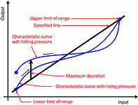
The conformity error is quoted as a numerical value in percent of the full-scale deflection and usually specifies the maximum deviation of the measured characteristic curve from the ideal line between the start and end of the measurement. This is possible because DIN states that only the maximum single error from linearity, reproducibility and hysteresis is decisive for the conformity error. With modern sensor systems, hysteresis and reproducibility are negligible.
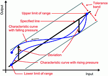
In the case of imported pressure measuring converters, the conformity error is often accompanied by the abbreviation BFSL (best fit straight line). This measuring method, also known as the tolerance band method, calculates the initial lines, which are then applied to the actually measured values to keep the deviations as small as possible. This method is also accepted by DIN16 086 as a specification, but the method of determination must be quoted. Often this is not done, however, which means that it is usually impossible for the user to compare the quoted levels of accuracy. As a rule of thumb it is possible to quote a factor of two for the difference in accuracy between limit point calibration and minimum value calibration (1% with the limit point calibration method equals approximately 0,5% with minimum value calibration in accordance with BSFL).
Hysteresis
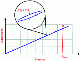
Hysteresis is the difference observed in the output signal when the pressure applied is in the process of rising or falling through the value being measured. With diaphragm deflections in the mm-range, today's sensor technologies usually have hysteresis values of significantly less than 0,1%.
Temperature ranges
Process fluid temperature
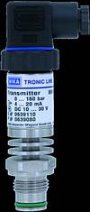
The process fluid temperature defines the range of temperature that the process fluid may take on without the pressure-measuring converter departing from its quoted specifications. Pressure measuring transducers with an integrated cooling section are used if the process fluid temperatures are high, eg up to 150°C (Figure 5). Chemical seals need to be fitted for process fluid temperatures of up to 400°C.
Ambient temperature
The ambient temperature defines the range to which the pressure measuring converter can be exposed without it departing from its technical specifications and suffering any damage to its casing or electrical connection.
Compensated temperature range
The most important item of data for the permissible temperature limits is the compensated temperature range. The temperature errors with corresponding temperature coefficients quoted in the specifications apply within these limits. This is where mistakes are often made if it is assumed that no additional temperature error occurs in the compensated range. In practice this means having to add the temperature error with its temperature coefficients to the error quoted as class accuracy when operating under changing temperatures. The coefficients depend mainly on the sensor systems used and are conditional on the corresponding internal compensation.
Individual compensation data for each particular pressure-measuring converter can be established by an analog-digital circuit arrangement and be saved in the integrated memory. Compensated pressure measuring converters of this type display no additional temperature errors within a specially defined temperature range.
Forms of electrical connection
Among electrical connections there is a continuing trend toward using 4-pole right-angle plugs in accordance with DIN 43659. Today the most popular choice for low-price pressure measuring converters are 6-4A 1 MMT appliance plus. Installation and replacement is far easier with both of these plug systems than with cable outlets, for example.
Cable outlets are needed if the plug systems are unable to meet the requirements on protection standards. This is nearly always the case with so-called well probes or level probes. Here the demand for water-tightness at submerged depths of up to 250 m can only be met by means of specially designed cable outlets (glands).
For more information contact: Greg Rusznyak, Wika Instruments, tel: 011 621 0000.
| Tel: | +27 11 621 0000 |
| Email: | [email protected] |
| www: | www.wika.co.za |
| Articles: | More information and articles about WIKA Instruments |

© Technews Publishing (Pty) Ltd | All Rights Reserved