



I am often astounded by finding really basic problems with controls in plants, which have operated that way for years. These problems are so basic that one can only wonder at how these controls could have been commissioned in the first place, as personnel in these plants are usually highly trained. Two examples I recently came across when performing some optimisation work at a large chemical plant are described in this article.
Example 1
The first example is of a gas pressure control that used two split range valves. The valves were effectively in parallel and supposed to operate as follows:
• Valve A is to open 0 – 100% when the PD (controller’s output) goes from 0 – 50%.
• Valve B is to open 0 – 100% when the PD (controller’s output) goes from 50 – 100%.
Split ranging of valves often causes problems with controls for various reasons, particularly at the ‘cross-over’ point, where very careful calibration of the valves is required to ensure that the one valve will take over smoothly from the other. (Another common problem is that split ranging is done without ensuring that the process gain remains constant over the full travel of both valves. If this is not the case, then different tuning will be required for both of the ranges. However, it was not a problem in this case.)
In this example, there was a problem trying to keep the pressure constant at the process load conditions operating at that time. Normally operators overcome control problems by running a loop in manual. However in this case, they were really battling to achieve control.
A young control engineer in the plant had been tasked to tune the controller and had been battling for some time. Pressure control can be quite difficult to optimise on occasion, as gaseous pressure processes can be self-regulating or integrating depending on various factors in the process. In this case the tests quickly established that the process was a fairly fast integrating one. However, whatever she did to try and get an open loop test with a proper response representing the process dynamics did not seem to work, and it seemed impossible to get the process into balance.
[Note: an integrating process, which is similar to a level control, is only at a constant state when the input to the process is equal to the output from the process. The value of the PD (controller’s output value) at that point is known as the balance point.]
When we started analysing the loop in more detail, it was decided to check if the valve split ranging was working correctly. At the load conditions at the time the tests were being done it appeared as if the balance point on the PD was probably between 50 and 60%.
Very fortunately we found that there was a flowmeter some distance downstream from valve B, and this enabled us to monitor the actual valve performance. A portion of this test is shown in Figure 1, where the controller was in automatic and the PD was increasing slowly. It can be seen that the flow through the valve was initially at zero. As the PD moved past 50% the flow should have started moving. However, it remained at zero which means the valve was not moving. The valve only started moving when the PD got to 75%.
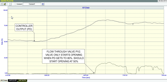
This means that from 50 -75% of the PD, there was no control action. What had happened, which is something I also saw once many years ago, is that someone had tried doing the split ranging on the valve’s positioner, not knowing it had been done in the DCS. In other words the positioner had been programmed to only start opening the valve when its actual input reached 50%.
No wonder there was no control in automatic or in manual as there is a 25% gap where the valve did not move at all! The interesting thing is that this plant has been running for years with this problem, and it didn’t seem to have been noticed until lately. It really boggles one’s mind.
Example 2
The next example is also very interesting. It is of a simple flow control loop, which always had to be operated in manual, as it just would not work in automatic. The figures shown for this example are made from simulated tests, as it would have taken far too much time to actually perform them in real time.
Properly tuned flow loops generally respond to a setpoint change in a few seconds. In this case, if we had performed a closed loop test on the loop with the existing tuning as set in the controller, it can be seen in Figure 2 that it would have taken approximately 5 hours for the loop to respond fully to a 10% setpoint change. This is obviously why they were always running the loop in manual.
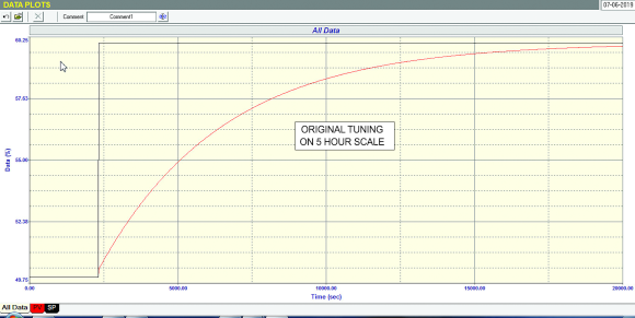
The open loop test on the flow showed that the valve was almost twice oversized and had an extremely fast response. However, these things are not a problem, and in fact the valve was working very well. No other problems could be seen from the test. Therefore, there must have been something wrong with the tuning. The young engineer who was doing the optimisation had checked the existing tuning that was in the controller. It was supposed to be P gain = 0,2, and I = 0,2 minutes/repeat. These are not unreasonable figures for a fast flow loop.
Further investigation showed that the problem lay in the set-up of the control module. This was because the control system, for some reason, only allows one to insert a minimum proportional gain of 0,1. There are times when one needs a much smaller gain particularly when the final control element is oversized, and the process is fast, like a flow loop. In the particular control system used in the plant, this problem could be overcome by using a controller module with a special gain reduction factor, whereby one can reduce the gain by an additional factor over the whole range of the control.
For some reason this module had been used in this loop, and we found that the gain reduction factor had been set at 0,1. This resulted in an effective proportional gain in the controller of 0.02, which is almost like switching the controller off.
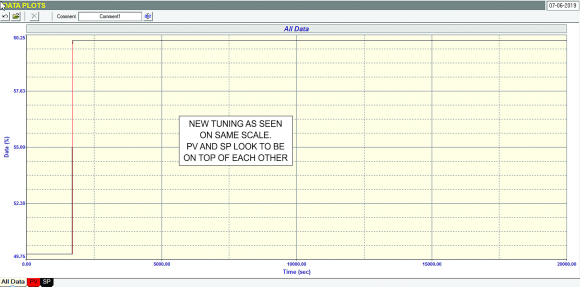
Setting the gain reduction factor to unity enabled the module to operate like a normal controller, and with new tuning of P gain = 0,6, and I = 0,1 minutes/repeat solved the problem and enabled the controller to work properly, allowing the process to respond to set point changes in a few seconds as should be the case for flow loops. The response with the new tuning is shown on the same time scale as in the previous figure is shown in Figure 3.
Such basic and simple errors caused huge control problems. Really amazing!

Michael Brown is a specialist in control loop optimisation with many years of experience in process control instrumentation. His main activities are consulting, and teaching practical control loop analysis and optimisation. He gives training courses which can be held in clients’ plants, where students can have the added benefit of practising on live loops. His work takes him to plants all over South Africa and also to other countries. He can be contacted at Michael Brown Control Engineering cc, +27 82 440 7790, michael.brown@mweb.co.za, www.controlloop.co.za
| Email: | michael.brown@mweb.co.za |
| www: | www.controlloop.co.za |
| Articles: | More information and articles about Michael Brown Control Engineering |






© Technews Publishing (Pty) Ltd | All Rights Reserved
 printer friendly version