

How well are industrial feedback control loops (often referred to today as the base control layer) working? I and several other colleagues who work in various countries around the world, and who between us have optimised many thousands of loops, have found the following state of affairs:
* Approximately 85% of most loops operate completely inefficiently in automatic.
* At least 50% of loops have problems in them which can include valve problems, measurement problems, design faults, and process problems amongst other things. In most cases plant personnel are often not even aware these problems exist.
* Less than 5% of the loops could be said to be working really well in automatic.
* Only about 5% of loops are tuned even close to optimum, most being so slow they cannot respond quickly enough to deal with changes which can be caused by set point or load changes. (Load changes are those that cause the PV (process variable) to deviate from set point due to causes outside the loop, such as change of pressure in the pipe that contains the control valve.
* Most plant personnel believe any loop problem can be solved by tuning, which is the number one biggest fallacy in control ideas.
Lack of proper understanding
The main reason for this deplorable state of affairs is that very few people understand the basic principles of practical process control, which is a subject that is hardly ever taught. Most control courses are heavily mathematically orientated, and offer no insight into the practical aspects of control. As a result most beginner control practitioners come out of their universities or colleges to find that it is almost impossible to apply this theoretical learning. They then proceed to learn by ‘trial and error’, and many, if not most, develop ideas and beliefs which often are erroneous.
As mentioned above, at least 50% of loops have problems, and about 85% of the problems in these loops are due to valves that are not operating correctly. The purpose of the final control element in a control loop is to ‘translate’ the signal coming from the output of the controller which we call the ‘Process Demand’ (PD) into a practical flow of whatever is passing into the process. The PD signal is the result of the controller’s calculation to determine what amount of product should be put into the process to ensure the process variable stays or gets to set point, and to keep control variance to a minimum. However, as the controller can only put out an analogue or digital electric signal, it is up to the final control element to actually produce the correct flow by ensuring the right amount of fluid or product as dictated by the PD.
The purpose of the final control element
In real life, about 90–95% of all final control elements are valves, mostly they are pneumatically operated. Unfortunately these are the weakest element in the control loop.
Most modern measurement transmitters are very good with the latest scientific developments incorporated into them, and they generally do a good job provided they are installed and used correctly according to their manufacturer’s specifications. Also most modern transmitters are ‘smart’, incorporating all sorts of clever computer programmes that add to the integrity of the measurement. In general if they are used correctly one can rely on the measurement.
Modern controllers are software-based on highly sophisticated powerful computers. Again, provided they are set-up correctly (which is often not the case, particularly in PLCs) they also do a fine job, giving accurate calculation of the PD. This calculation is based on mathematical formulae which were developed by some if the world’s most eminent mathematicians. I still find it literally awesome, to see how well the maths works if the control loop is set up correctly.
The last element for control in the loop is the valve, which is a mechanical device, and with all due respect to valve designers, whom I admire immensely, valves are subject to all the limitations and problems that any mechanical device is naturally subjected to, particularly in the case of many industrial processes which can have difficult fluids which may be corrosive, abrasive, viscous, etc. They also are subject to mechanical wear, hysteresis, non-linearity, high pressures, frictional forces and many other problems.
As mentioned, the valve’s job is to translate the process demand signal into an actual flow of fluid. There is no doubt at all that if the valve follows the controller’s dictates reasonably well then control can be good, but if it doesn’t then the control will be bad.
Unfortunately, the personnel in most instrument maintenance departments do not have the skills or equipment to really set up valves to give good control. It is a highly skilled job which needs to be undertaken by people with a deep understanding of the valves and a lot of experience. Recently, I had a talk with the head of control of a group of 40 chemical plants in the USA. He told me that they have now decided that they are no longer going to perform control valve maintenance internally in any of their plants, as it is too specialised, and they are now contracting it out to specialist companies in the control valve field.
People that follow these articles will be aware that most of them are about valve problems. This is because I come across problem valves so frequently, and it still fascinates me after all these years to find so many valves with peculiar behaviour, which will obviously limit or even prevent good control. I often tell the delegates on my courses that I doubt if I would be teaching them if it wasn’t for valves, as control would be so much easier if valves were perfect.
A practical example including ‘negative hysteresis’
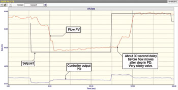
This article tells about a very good example of a flow control valve with many problems which was causing continuous cycle. Figure 1 shows the closed loop test as found where step changes in set point are made with the original tuning as found in the controller. The original tuning had a proportional gain of 0,15 and an integral of 1 minute per repeat, which is really poor tuning for flow loops relying almost purely on the gain with the integral action far too slow.
Two things of interest can be seen in the test. The first is that the valve is extremely sticky. It takes the positioner over 30 seconds to get the valve to move after the set point is stepped. Secondly, it would appear that the valve is about six times oversized. This can be seen by the relative sizes of the steps in PV and PD. They should ideally be about the same size. A valve that is six times oversized is very bad, as control variance is multiplied by the oversize factor. Apart from this it can be seen that the PV never actually gets to set point. This is as a result of the incredibly slow integral. (The purpose of the integral term is, of course, to eliminate error).
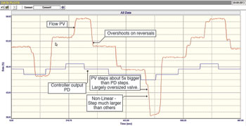
Figure 2 shows the open loop test. The findings in the first test are confirmed in this test with the valve again taking about 30 seconds to move after each step was made on the PD. Also it can be seen that at times the valve actually sticks during the step and then the positioner has to get it to move again. The huge oversize is again confirmed by looking at the PV and PD steps sizes. However, of even more concern, is that the valve overshoots on each reversal and ends up further than the step preceding the reversal. This is known as ‘negative hysteresis’, a very bad thing as valves with large negative hysteresis like this usually end up continuously cycling when the controller is placed in automatic with good tuning.
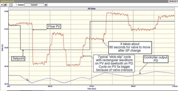
Negative hysteresis is caused by either an undersized (under-powered) actuator, and/or positioner problems. Figure 3 shows the final closed loop test with proper tuning with a proportional gain of 0,02 and an integral of 0,10 minute per repeat. It can be seen as suspected, that a continuous cycle exists, with a rectangular type of waveform on the PV and a saw tooth waveform on the PD. This type of cycle is referred to as a ‘stick-slip’ cycle, of which this is an excellent example. The period of the cycle is about three minutes, and this very slow type of cycle is usually due to an undersized actuator. The amplitude of the PV cycle is about 5 to 6 times larger than it would have been if the valve had been properly sized.
The sad thing about cycles like this is that about 99% of people believe it is caused by bad tuning, and do not realise that seriously bad valve problems exist. I am commonly told that it didn’t cycle with their tuning. However, if you want to stop a loop cycling then you place it in manual. Manual control is the ultimate slowest tune. If you tune a loop slowly enough it will eventually stop cycling, but it cannot catch changes. Just out of interest, if loops cycle due to bad tuning, they usually cycle close to their ultimate period which in the case of flow loops is usually around 6–10 seconds. Certainly not three minutes. This is the reason that the original tuning was so slow. The people doing the tuning kept on slowing it down until the cycling stopped. We often refer to this as ‘tuned into manual’.
There is usually no easy solution to stick-slip cycling caused by negative hysteresis. Generally the problems in the actuator, valve and positioner have to be fixed. Until then the valve will continue its dance.

Michael Brown is a specialist in control loop optimisation with many years of experience in process control instrumentation. His main activities are consulting, and teaching practical control loop analysis and optimisation. He gives training courses which can be held in clients’ plants, where students can have the added benefit of practising on live loops. His work takes him to plants all over South Africa and also to other countries. He can be contacted at Michael Brown Control Engineering cc, +27(0)82 440 7790, [email protected], www.controlloop.co.za
| Email: | [email protected] |
| www: | www.controlloop.co.za |
| Articles: | More information and articles about Michael Brown Control Engineering |


© Technews Publishing (Pty) Ltd | All Rights Reserved
 printer friendly version