

I have performed loop optimisation in hundreds of plants in various countries and there are many myths and misconceptions that are common to them all. The worst is that all loop problems can be solved by tuning. In particular, there is the widely held belief that if a loop is cycling when the controller is in automatic, then that is entirely due to bad tuning.
In actual fact there are many reasons why cycling could occur, which include:
1. Stick-slip valve cycling due to an inherent valve problem, sometimes found on fast self regulating processes.
2. Valve hysteresis cycling on integrating processes tuned with P+I terms.
3. Cycling caused by negative hysteresis on a valve, can be caused by undersized actuators or positioner problems.
4. Unstable positioners.
5. Signal aliasing where the controller has a slow scan rate and can create a low frequency aliased signal which causes the valve to cycle. If the process is fast enough to react to these frequencies then it will also cycle.
6. Interactive processes can react with each other and cause cycling.
7. And, of course, bad tuning could also cause instability.
Operators place the loops in manual
As can be seen from six out of seven causes of cycling these have little to do with the tuning.
However, people can virtually tune any loop to stop it cycling. How do they do this? Easy. Operators know instinctively how to stop loops cycling – they place them in manual. One could define manual control as ‘the ultimate slow tune’. Therefore, if you detune (slow down) the control far enough, most loops will stop cycling. I have encountered many loops running unbelievably slowly in automatic – virtually tuned into manual. In some cases on flow loops, I have found them tuned so slowly that they can take hours to follow a 10% set-point step change. This should happen in a few seconds.
Integrating processes, typified by levels, are notoriously associated with cycling. They can have numerous problems, and it is often very hard to perform fault finding on them. Many of my previous articles, particularly in the two Loop Signature series, discuss the reasons for this. This is contrasted by self-regulating processes which are much easier to analyse and uncover the faults.
The vagaries of integrating processes
One of the main problems with integrating processes is they have a natural tendency to be cyclic, thus they are often found to be cycling continuously and often very slowly. These cycles can sometimes literally have periods of hours in processes with very small gains (long retention times). The main reasons for such cycling are either bad tuning, as very few people understand the characteristics of integrating processes and how to tune them, or hysteresis on the valve. (Integrating processes which are tuned with P+I parameters, which is the case in probably 98% of all control loops, and where there is hysteresis on the valve will cycle continuously.)
The main reasons why integrating loops behave as they do are:
1. Integrating processes start out with the process variable lagging 90° behind the process demand (controller output).
2. The phase plot of integrating processes tuned with P+I terms in the controller is pulled down at low frequencies. This means that a well tuned controller is actually only a little way from instability at low frequencies, which accounts for the slow cyclic behaviour of these control loops.
One can perform open loop tests on self-regulating processes using numerous steps. These allow for easy analysis of valve faults like hysteresis, non repeatability and non-linear installed characteristics. However, integrating processes are only constant when the input to the process equals the output from the process – known as a ‘balanced’ process. Thus one can only make one step away from the balance, as the process then ramps and this will continue until it reaches either 100% or 0% of the measurement. This does not allow one to do much fault analysis. Therefore, if one finds an integrating process cycling continuously and if the tuning is reasonable, then one can suspect that there is a valve problem, but it is hard to prove.
Real world example
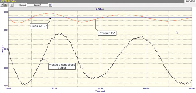
In the example presented here, an integrating pressure control loop was found to be cycling continuously. The closed loop test after tuning is shown in Figure 1. The loop is cycling with a period of about 8 minutes. The open loop test on the pressure loop did not reveal any problems. Fortunately, after examining the loop drawings, it was seen that there was a flow transmitter in series with the control valve.
An open loop flow test was then performed on the flow through the valve. This is shown in Figure 2, and really shows a remarkable picture of a valve in a very bad way. Small 1% steps are being made on the PD (controller’s output). When the steps are increasing, the valve only moves after several steps have been made. Once it moves it moves in extremely large steps. On closing it sticks on the reversal and then does move. However, the valve movements are of different sizes, meaning that the valve is non-repeatable. Hysteresis of approximately 4% can also be measured in the test.
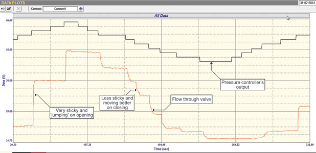
There is no way that one can perform any reasonable control with such a bad valve.
The valve is the reason that the pressure loop is cycling. The only thing that could be done is to fix the valve.
A point of interest is that as the flow through the valve has already been measured, then the flow loop should have been configured as a cascade secondary to the pressure. There is a strong possibility that even with the bad valve performance better control of the pressure could have been obtained. (The cascade secondary flow loop would now be self-regulating, and this class of process does not inherently cycle with valve hysteresis and P+I tuning).
There is no way that we could have analysed this fault directly on the integrating pressure loop. We would have suspected a valve problem but would not have been able to prove it.

Michael Brown is a specialist in control loop optimisation with many years of experience in process control instrumentation. His main activities are consulting, and teaching practical control loop analysis and optimisation. He gives training courses which can be held in clients’ plants, where students can have the added benefit of practising on live loops. His work takes him to plants all over South Africa and also to other countries. He can be contacted at Michael Brown Control Engineering cc, +27(0)82 440 7790, [email protected],
| Email: | [email protected] |
| www: | www.controlloop.co.za |
| Articles: | More information and articles about Michael Brown Control Engineering |


© Technews Publishing (Pty) Ltd | All Rights Reserved
 printer friendly version