

For an explosion, all three of gas/dust, oxygen and source of ignition (spark or heat) need to be present. Intrinsic Safety (IS) works on the principle of removing the source of ignition. This can be achieved by using a Zener barrier or galvanic isolator.
The three principles of Ex i design are defined as follows:
1. Limit current.
2. Limit voltage.
3. Limit stored electrical energy.
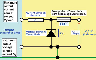
A Zener barrier is a simple device where the voltage and current (power, energy) is limited into the hazardous area. The voltage is limited (clamped) by a Zener diode and the current limited by an output resistor. The fuse is there to protect the Zener diode. The key to safety is the intrinsically safe (IS) earth. Without it, there is no protection. These components are all ‘Safety Components’ meaning components upon which safety depends. The Zener barrier is usually designed for zone 0 connectivity [Exia] and can then be used for zone 1 [Exib] and zone 2 [Exic]. For Exia, the Zener barrier has to be safe with two faults, so the safety components have to be assessed to ensure they cannot fail unsafe. This is achieved through duplication of Zener diodes. Safety components also have a 1.5 safety factor which means that under fault conditions, they never dissipate more than 2/3 of their commercial rating.
Modes of operation
When Zener barriers are used, they need to be considered in 2 modes: fault condition and operational.
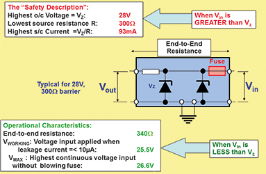
1. In a fault condition, the input voltage Vi to the Zener barrier is higher than the Zener voltage Vz and the Zener barrier has to ensure that the output to the hazardous area is limited for safety. Under these conditions, the ‘Safety parameters’ Uo, Io and Po are the only parameters applicable. These parameters have nothing to with operational characteristics and define the maximum output power/energy into the hazardous area. This is accomplished by the Zener diode(s) conducting and diverting all current to the IS earth. If this condition is maintained, the Zener diode(s) is likely to blow, so the fuse is there to protect it.
2. When operational, Vin is always less than Vz and minimal current flows through the Zener diode(s). In this situation, the loop designer needs to take account of end-end resistance, maximum voltage at the input terminals and leakage current through the Zener diodes. A calculation has to be done to ensure that there is sufficient voltage at the field device for it to function (don’t forget additional voltage required if Hart is being used). So the voltage at the transmitter will be Vin – (Iloop x loop resistance). The loop resistance is the end-end resistance plus cable resistance. This can be quite tight and as this is not an issue for galvanic isolator (no end-end resistance), it makes using isolators easier.
In a current loop, leakage current through Zener diodes can affect accuracy. Vworking is defined as maximum voltage at which leakage current is less than 10 μA. Vmax is defined as maximum voltage that can be applied continuously at the input terminals such that the fuse will not blow.
For further information on product selection and loop approval, please refer to http://www.instrumentation.co.za/7571a
Conclusion
Zener barriers are an older and proven way of implementing intrinsic safety with a huge installed base in South Africa and the rest of the world. The requirements for an IS earth and the calculations of voltage drop and loop voltage make it less flexible than using galvanic isolators. Although Zener barriers are cheaper, for a green field site (or a site that does not have an IS earth), the cost of ownership (installation and maintenance) of an IS earth makes isolators a better option.
IS offers a simple and flexible solution for zone 0, 1 and 2. It is the only protection that considers faults of the field wiring and offers live working without the need for a gas clearance certificate. It does require some design and planning to ensure that the system loop analysis is acceptable.
Zener barrier components are carefully specified and selected to ensure safety and operation. Components cannot be replaced. Once a Zener barrier has done its job and the fuse is blown, a replacement barrier is required.
IS allows live working so careful attention has to be taken to ensure than the Zener barrier is ‘short circuit proof’. i.e. the fuse must not blow when a short circuit is applied at the hazardous area terminals.
Zener barriers are normally encapsulated. This is done for heat dissipation under fault conditions and also prevents tampering with safety components.
IEC/SANS60079-11 Table A2 defines the maximum output capacitance Co for a defined safety voltage Uo. Gas group and zone also have an impact on this value.
Remember:
1. Using Zener barriers without an IS earth is not safe!
2. Inserting a barrier or isolator with a non-certified (active) field device is not safe!
For more information contact Gary Friend, Extech Safety Systems, +27 (0)11 791 6000, [email protected], www.extech.co.za
| Tel: | +27 10 055 7300/1 |
| Email: | [email protected] |
| www: | www.extech.co.za |
| Articles: | More information and articles about Extech Safety Systems |


© Technews Publishing (Pty) Ltd | All Rights Reserved
 printer friendly version