

Feedforward control was explained in the previous loop signature articles, and one of the examples used was feedforward control of load changes on a heat exchanger when variations occurred in the flow of the process fluid through the exchanger. A change of flow in the process fluid affects the temperature, and it was shown how feedforward control could immediately compensate for such a load change. In fact, if it could be perfectly applied, it would operate with zero variance.
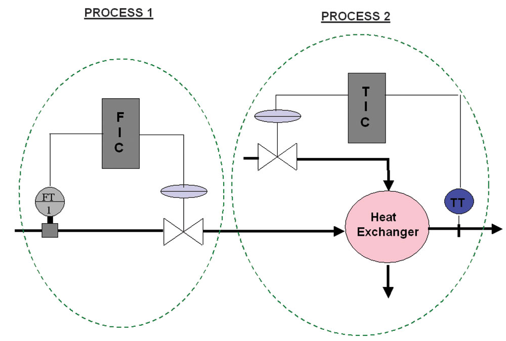
Figure 1 shows a similar heat exchanger. In this case, there is a flow control loop upstream of the exchanger which could regulate the flow of the process liquid through the exchanger. The loop has been labelled in the dotted boundary line as Process 1. The actual temperature control loop in the exchanger has been labelled Process 2. Now, if Process 1 changes and the flow changes, it will have an effect on Process 2. We can say that Process 2 is ‘coupled’ by Process 1.
If we play around with the steam valve in Process 2, it will have no effect on Process 1, the process fluid flow, so we can say that Process 2 does not couple Process 1. The system is referred to as a ‘1 x 2 coupled system’.
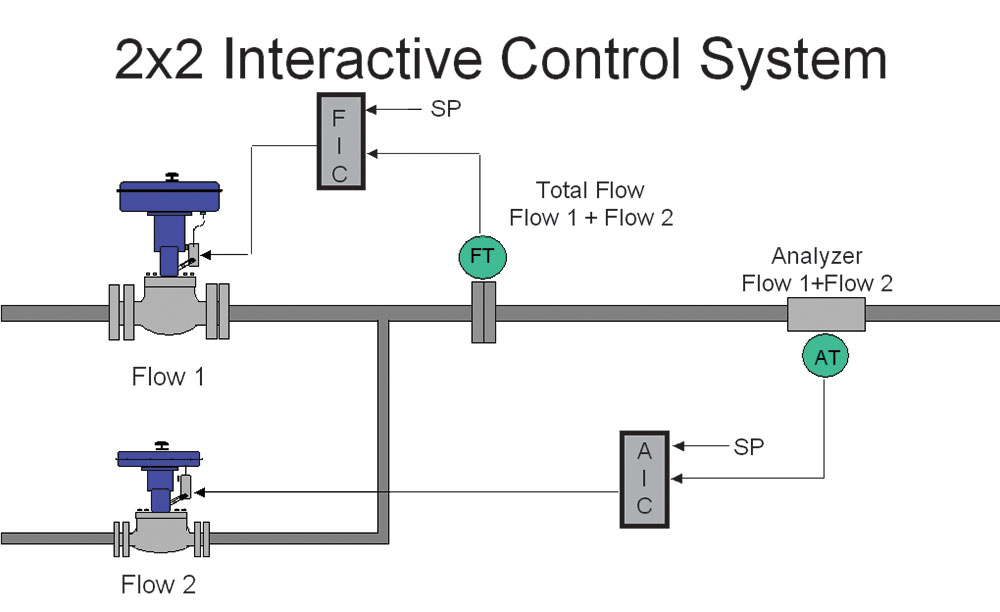
Now, have a look at Figure 2. Here, two flows are joined together, the one being a product, and the other, some sort of reagent to adjust the chemical property of the product. Let us say it is pH, which would be typical. There are two control loops in the system. The first, Process 1, measures and controls the total flow of the combined product and reagent leaving the system, and the second, Process 2, measures and controls the pH of the mixture.Now it is fairly obvious that if the valve of Process 1 changes, it will affect both the total flow and the pH. Similarly, a change of the valve in Process 2 will also affect both the total flow and the pH.
When two processes have a mutual affect on each other like this, they are coupled in both directions, and that they are interactive. A system with like this one is referred to as a ‘2 x 2 interactive system’.
In general, interactive systems will tend to ‘fight’ each other, particularly if both loops operate at the roughly the same speed. A very good measure of the loop speed is the ultimate period. In the Loop Signature 22 article from the first Loop Signature series, we showed that when a repetitive disturbance with a period of 0,2 to 6 times a feedback loop’s ultimate period affects the loop, control variance is higher in automatic mode than in manual mode. Highly interactive loops generally have similar ultimate periods.
When we dealt with a 1 x 2 coupled system in the previous Loop Signature articles, we referred to the one process as ‘the process’, and the other as ‘the load’. This will not make sense in an interactive system where we have two definite processes, because each of them could be referred to as ‘the load’ on the other. Therefore we refer to the transfer functions of each process and each ‘load’ on the other as ‘couplers’.
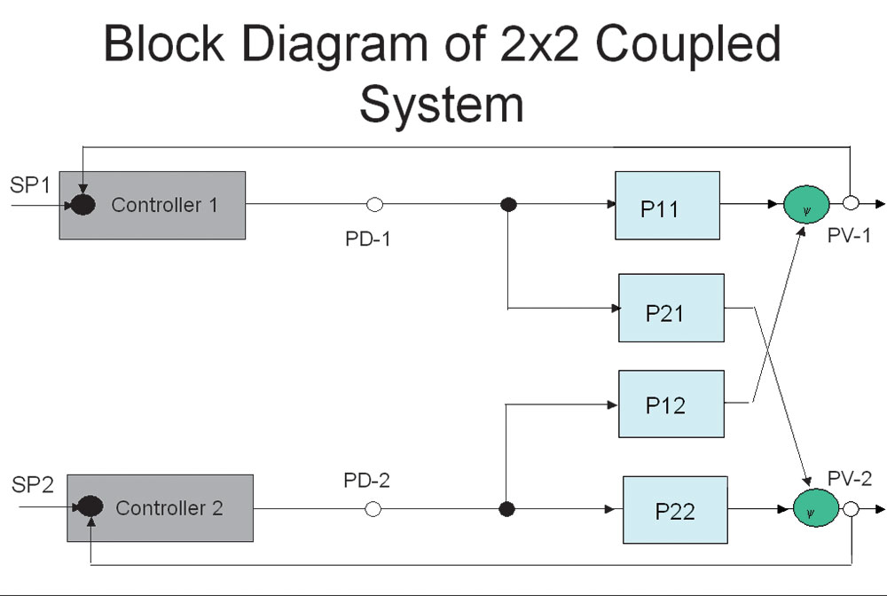
In the block diagram shown in Figure 3, we can see how much easier it is to understand how the system works with the various couplers. PV1 is coupled by both PD1 and PD2 through couplers referred to as P11 and P12 respectively, and similarly, PV2 is coupled by both PD2 and PD1 through couplers referred to as P22 and P21 respectively.
But systems may interact with varying degrees of intensity. Imagine that Flows 1 and 2 in Figure 1 were in pipes of the same diameter and were of comparable flow volumes, then in this case, the system would be highly interactive. A change in either valve would have a significant affect on the other’s PV as well as on its own. However, in reality as in the case of pH control, the reagent is usually supplied in a pipe much smaller than the process flow, and the volume through the reagent’s valve is relatively tiny compared with the process flow. In such a case, a change in the flow of reagent will have a large effect on the pH (Process 2), but will have a very small effect on the total flow (Process 1). Conversely, a change in Process 1’s valve will have a significant effect on both the total flow and pH.
This latter case would not present such a difficult control problem as the first case where the system is very interactive. It is therefore quite important to first establish the degrees of interaction between the processes. This can be accomplished by putting both loops into manual, and then, to step each PD alternatively, keeping the other one constant.
For interest sake, the scientific way of establishing the degree of interaction is by using something called a ‘relative gain array’. However, in practice, it is easier to use one’s intelligence when dealing with a simple thing like a 2x2 coupled system.
Interactive loops of various complexities are encountered often in many types of plant. However, one does find many interactive loops in particular plant types like boilers and distillation columns. Here, many loops in different sections of the plant may interact, and in some cases, it is so bad that if good control is required, it becomes imperative to use advanced control techniques to decouple the interactive loops. One such technique is multi-variable control. We will discuss the basics of this a little bit later.
In most plants, we often encounter interactive loops, and an example of loops like those are shown in Figure 2. Another very common one is where gas or steam first passes through a pressure control valve to control the downstream pressure before passing through a flow control valve, as is often found in steam or gas headers. Such a system is shown in Figure 4. In most of these cases, it would be uneconomic to purchase an advanced control scheme just to sort out these few loops, therefore, one generally tries to minimise the interaction by tuning. The technique for tuning will be discussed first.
Decoupling by tuning
Operators through the ages have found that the best way to decouple interactive loops is to place one or more of them into manual, and by doing so, the interactive loops can’t fight each other any more. This is the ultimate method of decoupling.
Unfortunately, feedback control cannot deal effectively with interactivity. As I mentioned earlier, if two or more loops are in a configuration where interaction can occur, and they have similar ultimate periods, they will fight each other.
We are going to discuss a 2 x 2 interactive system. The only way to try to decouple the two loops through tuning is to make them respond at different speeds. One loop must therefore be tuned fast and the other slow. Keep in mind that the slower a loop is tuned, the closer it moves toward manual operation, which can be regarded as the ultimate slow tuning.
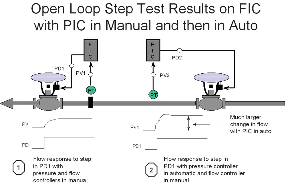
One of the problems associated with interactive loops most people are not aware of is that the dynamics of each loop will change if the other loop is in automatic or in manual. To illustrate this, refer again to Figure 4 which shows two potentially highly interactive control loops, or high-pressure gas flows down a line. Firstly, it passes through a flow control loop to reduce the pressure to a useable level, and secondly goes through a flow control loop to keep the flow constant. As mentioned earlier, this is a common arrangement seen in plants, particularly when there are several flow loops being taken off a header. The loops can become interactive if there is insufficient capacity in the line between the two valves to allow pressure and or flow changes to occur slowly.
It can be seen in the figure that if an open loop step test is performed on the flow loop with the pressure controller (PIC) in manual, the PV responds, as shown in Note 1. However, if PIC is in automatic, there will be a completely different response when the test is repeated on the flow loop, as seen in Note 2. In practice, each loop must be tuned while the other remains in automatic. If both loops are in automatic and one is then switched to manual, the other loop’s response will change, becoming either slower or faster and potentially unstable.
The procedure for decoupling by tuning is as follows, with reference being made to the system shown in Figure 2.
• Decide which loop must be the fastest, say FIC in this case
• Place both loops in manual, do normal analysis, and determine initial tuning for both
• With FIC in auto and AIC in manual, determine new tuning for AIC
• With AIC in auto, put FIC into manual and retune it
• If necessary, slow down AIC even further with an input filter, and remember, the maximum TC should not exceed 10 x DT of the analyser loop
• Repeat last 2 steps.
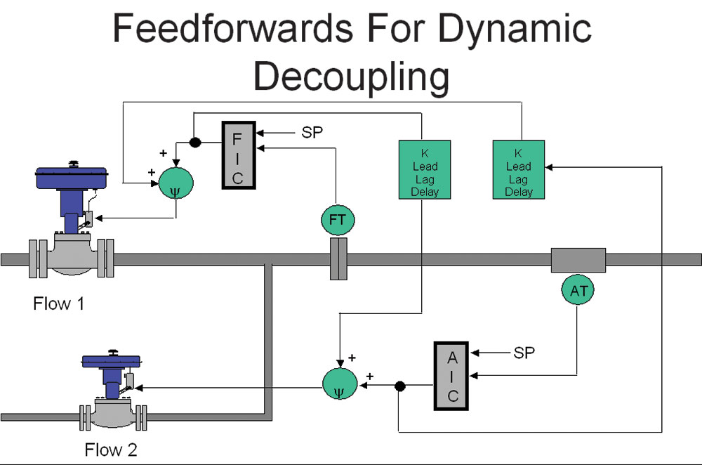
This is all that can be done to decouple interactive loops by tuning, and in reality, one can get away with this type of approach in many cases. However, in certain cases where the controls are very important and possibly very interactive, a more drastic measure must be employed. This is known as dynamic decoupling and is basically feedforwarding the changes occurring in each loop across to the other, as illustrated in Figure 5.
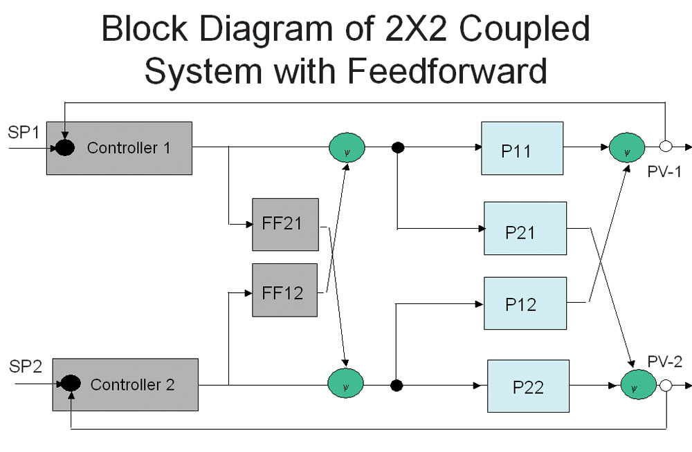
Figure 6 shows this in a block diagram format. The feedforward modules FF12 and FF21 are referred to as ‘decouplers’.
The procedure to perform the tests needed to establish the transfer functions of the couplers and to tune the decouplers employs exactly the same techniques shown in the preceding Loop Signature articles on feedforward. The tests are conducted as follows:
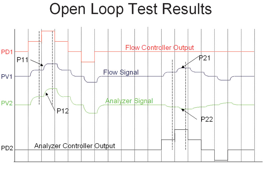
Referring to Figure 7, one records the response on both loops to step changes made on the outputs of each loop, one being changed at a time. Now we have the information to establish the following four transfer functions which follow the exact simple procedures as described in Loop Signature P2-3:
• P11 (PD1 vs PV1)
• P21 (PD1 vs PV2)
• P22 (PD2 vs PV2)
• P12 (PD2 vs PV1)
The gain, time constant and deadtime of each transfer function can be determined by either simple graphical analysis or by using an analyser, like the Protuner.
FF12 = P12/P11
K = PG12/PG11
Lead = TC11
Lag = TC12
Delay = DT12 - DT11
FF21 = P21/P22
K= PG21/PG22
Lead = TC22
Lag = TC21
Delay = DT21 - DT22
The advantages of using dynamic decoupling are:
• Coupled loops are tuned with the interactive loops in manual
• You only need to test the loops once
• Loop gains do not change when interactive loop in manual
• Both loops can be tuned fast
• Control system operations are not interactive
One can employ exactly the same techniques to decouple more complex systems like 3 x 3 systems. A delegate on one of our courses in the United Kingdom working for a large steel company used these methods to decouple a 4 x 4 coupled system. The method worked incredibly well, and he wrote a paper on it for a steel journal in Britain.
However, I personally think that when it starts getting to such complexities, it may be worthwhile to invest in a commercially available advanced multivariable control system.
About Michael Brown

Michael Brown is a retired expert in control loop optimisation, possessing over five decades of experience in process control instrumentation. His primary focus has been consulting and delivering instruction on practical control loop analysis and optimisation. He has conducted training and optimised control systems at numerous facilities internationally. Mr. Brown continues to author articles reflecting his extensive work, and his courses remain accessible for purchase in PDF format. Additionally, he manages the distribution of Protuner Loop Optimisation software and welcomes inquiries regarding loop-related issues.
Contact details: Michael Brown Control Engineering CC,
| Email: | [email protected] |
| www: | www.controlloop.co.za |
| Articles: | More information and articles about Michael Brown Control Engineering |


© Technews Publishing (Pty) Ltd | All Rights Reserved
 printer friendly version