Many of the unresolved or even undiscovered problems I find on faulty or badly performing control loops are due to a lack of knowledge, or lack of logical thought on the part of both C&I; (control and instrumentation) and process personnel.
I still find that the general prevailing ‘belief’ in plants is that any control loop can be made to work well by tuning it. If the tuning doesn’t fix the problem the usual comment is that “tuning is a black art and we’ll just keep on fiddling with knobs until it comes right.” Eventually they give up and the operators make changes in manual mode or just leave it in manual all the time.
Loop optimisation is, in fact, only successful when the control objectives are fully understood, the process dynamics are established and a thorough investigation is made of the loop to ascertain any faults and/or problems in the control strategy. Only when these things are done is one able to confidently apply scientific tuning to allow one to achieve the control objectives.
As many readers are aware from numerous articles I have published, generally the main problems in control loops are found in the final control element, which is usually a pneumatically-actuated valve. In fact I can confidently say that at least 75-85% of control loop faults occur in the final control element equipment, i.e., valve, positioner and I/P converter. Apart from this we do sometimes find problems in other loop components like the measuring system and very often with incorrectly configured control blocks (mainly in PLC control systems).
The example I am using for this article is a flow control loop in a metallurgical plant that was often in an unstable cycle when the setpoint was quite low down on the scale, which was the area where the loop operated most of the time. The plant’s C&I; personnel tried many different tunings to try and stabilise it, but it just kept on oscillating when at lower flows.
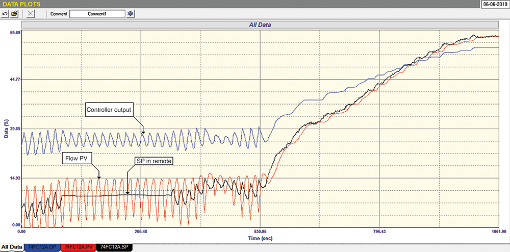
Figure 1 is a closed loop recording of the loop with the ‘as found’ tuning. It can be seen that the setpoint was coming from a cascade master controller, which was also interacting slightly with the flow loop, as it sometimes also cycled at the same frequency. However, when the setpoint started moving higher the cycle stopped and the controller managed to get the flow to follow the setpoint reasonably well, although very slowly and seldom actually got to setpoint.
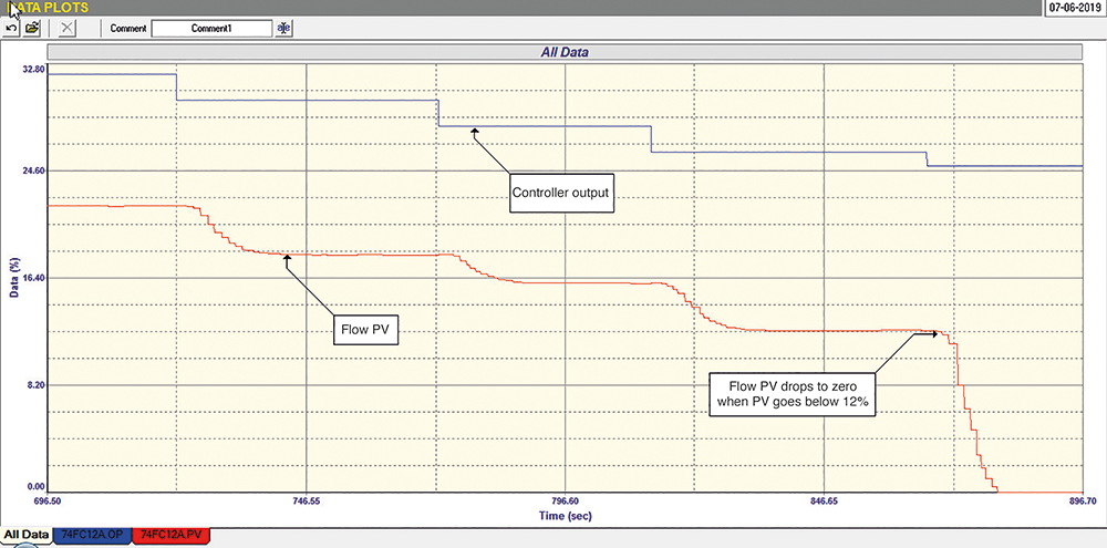 Figure 2. A portion of an open loop test performed on the flow control loop of Figure 1.
How does one go about trying to solve a problem like this? It is certainly not by playing with the tuning parameters. One must first analyse the components of the loop, which consist of the following:
1. Measuring transmitter.
2. Controller.
3. The operation of the process itself.
4. Control valve.
Normally to troubleshoot the loop one performs a closed loop test (like the aforementioned one) and then an open loop test (controller in manual) where several step changes are made on the PD (controller output). These two tests, if carried out properly, will generally give one all the information required to identify any problems and then, if they are not too severe, to apply scientific tuning.
Figure 2 is a portion of the open loop test that we performed on this flow control loop and reveals the following information:
a) The PG (process gain, which is the magnitude of the PV step size divided by the magnitude of the PD step size) is about 2,5 and this would suggest that the valve may be about 2-3 times oversized.
b) Based on the first three steps it looks like the valve has reasonable installed linearity.
c) Of extreme importance, it can be seen that the flow PV drops to zero when the flow goes below 12%.
d) The response of the PV to step changes on the PD is very much in the form of a first-order lag and is quite slow for a flow using a pneumatically-operated control valve. This would indicate that a lag filter probably exists somewhere in front of the PV input to the controller. It could be on the transmitter or in the control system. It was, in fact, found that a 3 s filter was inserted in the control system. Filtering is another subject about which I have written many times and is generally not recommended nor necessary.
One can now immediately understand why the loop was cycling in automatic when the setpoint was very low – as soon as the flow dropped below 12% the PV dropped to zero, so the controller then opened up the PD to open up the valve to bring the flow up. Once the flow got back past 12% and past the setpoint, the controller then tried shutting the valve to bring it down, which closed the PV down again and so it went on.
One must always ensure that the basics are correct. The first thing to check on here is what type of measurement technique was being used. In this case it was an orifice plate with a transmitter measuring the differential pressure across it. This type of measurement is one that goes back over several centuries and is still commonly used. Any C&I; practitioner will have studied the technology and there are many international standards dealing with it. However, to my amazement, I find that time and time again people are ignoring the basic rules and seem to think that because these days we are using ‘smart’ (computerised) transmitters, the basic rules can be ignored.
One of the general rules on differential head flow measurement, particularly using orifice plates as the primary element, is that they should never be used when the flow drops below 25%. In fact one of the standards actually recommends a lower limit of 33%. However, over many years it has been accepted that for control purposes a lower limit of 25% is acceptable.
There are many reasons for the low limit, one of which is that the flow is proportional to the square root of the differential pressure, which means very tiny differential pressure values at low flows, but there are other factors including the fluidic behaviour at low flows. In certain cases on certain fluids low readings can be completely wrong, let alone very inaccurate.
To try and prevent use of the transmitters at very low flows, most manufacturers of differential pressure transmitters have a low flow ‘cut-off’ incorporated into the transmitter, which these days the user can set. This is the reason why in this case the transmitter was cutting off at 12%. As can now be seen, the problem here was incorrect flow measurement. No tuning can overcome this problem.
I think this is another great example of the lack of practical knowledge displayed by personnel in many plants.
About Michael Brown

Michael Brown is a specialist in control loop optimisation, with many years of experience in process control instrumentation. His main activities are consulting and teaching practical control loop analysis and optimisation. He now presents courses and performs optimisation over the Internet. His work has taken him to plants all over South Africa and also to other countries. He can be contacted at: Michael Brown Control Engineering CC,
| Email: | [email protected] |
| www: | www.controlloop.co.za |
| Articles: | More information and articles about Michael Brown Control Engineering |


© Technews Publishing (Pty) Ltd | All Rights Reserved
 printer friendly version