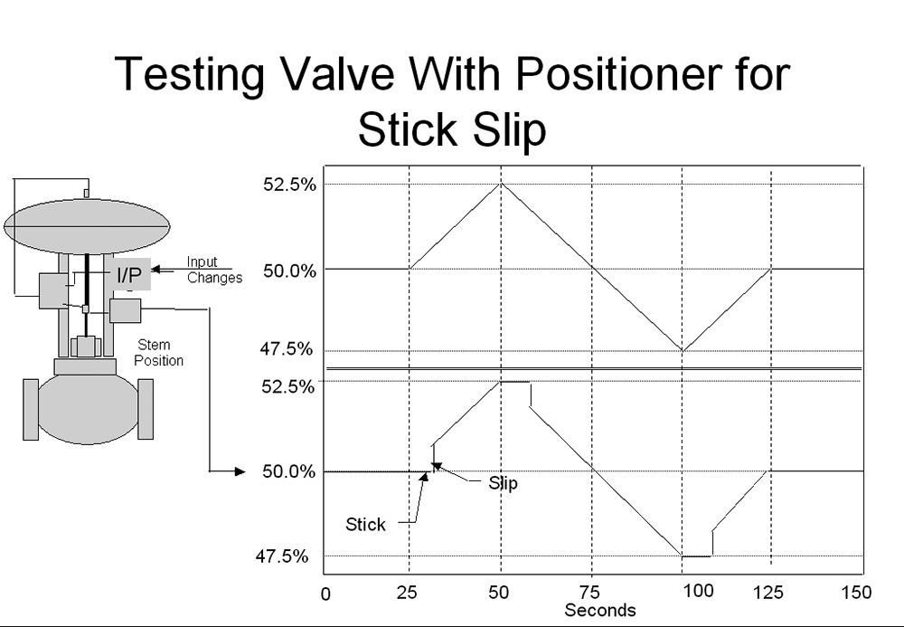
An inherent phenomenon occurring in most control valves that few people are aware of is ‘stick-slip’. This is illustrated in the test on a valve shown in Figure 1.
In this test, the input signal to the valve was ramped up 2,5% in 25 seconds, down 5% in 50 seconds and up 2,5% in 25 seconds. The ramp rate for the test was a 1% change in 10 seconds. This ramp rate change in valve position is therefore equivalent to a 100% valve change in 16,7 minutes, which in anybody’s reckoning can be considered as reasonably slow.
When the ramp initially started and every time it changed direction, the valve initially did not move and after a while gave a little jump or ‘pop’. This is known as stick-slip.
Cause
Stick-slip response in a valve is typically the result of a difference in the static and sliding friction in the valve assembly. It occurs mainly on valves positioned by means of diaphragm-spring actuators and is caused by an imbalance in the dynamic forces when reversing the valve. The first time the valve is moved in the opposite direction static friction arises, as explained in a previous article. The air pressure to the diaphragm is increased to overcome the static friction, as the valve cannot move until it is overcome. This is referred to as the ‘stick phase’. Once the static frictional force is overcome, the force necessary to move the valve further is now lower, since the sliding frictional forces are much smaller than the static frictional forces. At the instant static friction is overcome, there is still some remaining energy in excess, which is now pushing against the weaker sliding frictional force. This results in the valve popping to a new position. This is known as the ‘slip phase’.
Stick-slip, in general, has no serious effect on integrating or slower self-regulating loops, but is instrumental in creating a closed loop cycle, which is found on about 15% of all fast self-regulating loops that are tuned with a reasonable response.
Practical example
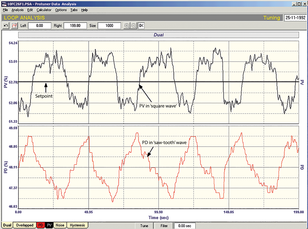
A typical stick-slip cycle is shown in Figure 2. This is a recording of an oil flow taken in a petrochemical refinery and is a final closed loop test after new tuning was inserted in the controller. At the start of the recording the PV (flow signal) is stationery at about 1% below set point and the valve is in the stick phase. The controller (PD) is trying to eliminate the error and its output is ramping upwards under the integral action. Eventually there is sufficient energy in the actuator to overcome the static friction and the valve starts moving, as can be seen by the rapidly decreasing flow. As the valve moves it also slips, and it ends up on the opposite side of the setpoint, where the whole process starts again in the reverse direction. This becomes a type of limit cycle, with a typically squarish waveform on the PV and a triangular waveform on the PD.
The reason why this is found mostly on fast self-regulating processes (typically flow loops), is because the ideal pole cancelled tuning for such processes is very low gain and fast integral. (On simple first order lag, deadtime, self-regulating processes, the integral is normally set equal to the dominant lag of the process). During the stick phase the integral term is ramping and in fact it pushes the controller output (PD) too far. This is effectively a little bit of controller ‘reset windup’, a subject which will be dealt with in detail in a future series of loop signatures on controllers. In any event this is a major factor contributing to the cycle.
The stick-slip cycle is most definitely a valve problem and not a tuning problem. However and very unfortunately, due to the general complete lack of practical control training by institutions who teach control, virtually nobody in the field is aware of this. As a result, whenever a stick-slip cycle is encountered in a plant (which, as mentioned above, can be on as many as 15% of all fast self-regulating processes), most people think it is unstable tuning and completely detune the loop until the cycle stops. At that stage, the control has virtually stopped as well. As a typical example, in the week I am writing this I have encountered three flow loops with inherent stick-slip cycles in a paper plant. On the closed loop tests with the original ‘as found’ tuning, they took close on an hour to respond fully to a 10% change of setpoint.
I have sometimes heard control engineers arguing that flow loops need not be tuned fast, as their speed of response is still much faster than general plant responses. If they believe that flow loops taking 20 minutes or longer to respond to a 10% setpoint change will not affect control, then I reject their argument absolutely. The function of regulatory control loops on continuous process plants is mainly to minimise variance at all stages of production. Typically, many flow loops are cascade secondaries which need to be much faster than their primaries. (By fast tuning I am not necessarily referring to quarter amplitude damped response, but typically tuning with the gain margin increased by 100% or more from this point). Our experience is that the improvement in performance of properly optimised plants is beyond most people’s belief.
It is common for people in this field to think that cycling in closed loop feedback control systems is caused only by unstable tuning. In reality and in our courses, we teach at least five different reasons for such cycling, which have nothing to do with poor tuning.
Solution
The solution to stick-slip cycling is a technique developed in the United States by David Ender of Techmation. He has given it the rather awkward name ‘Dead Band Reset Scheduling’, or DRS for short. One writes a relatively simple routine into the PLC or DCS, whereby a band can be placed equilaterally around setpoint, with amplitude slightly larger than the amplitude of the stick-slip cycle. The integral value (in terms of time per repeat) in the controller is increased by a factor adjustable from 1-20 inside the gap. Normally a value of 8 -10 suffices. Thus, although the response to small load changes is slower within the gap, any large load or setpoint changes that result in the PV moving out of the gap, are still dealt with speedily and the overall control variance is orders of magnitude better than completely detuning the controller.
About Michael Brown

Michael Brown is a specialist in control loop optimisation with many years of experience in process control instrumentation. His main activities are consulting and teaching practical control loop analysis and optimisation. He gives training courses which can be held in clients’ plants, where students can have the added benefit of practising on live loops. His work takes him to plants all over South Africa and also to other countries. He can be contacted at Michael Brown Control Engineering cc,
| Email: | [email protected] |
| www: | www.controlloop.co.za |
| Articles: | More information and articles about Michael Brown Control Engineering |


© Technews Publishing (Pty) Ltd | All Rights Reserved
 printer friendly version