

So many of my articles relate to valve problems that I just hope I don’t bore you, the readers, with the litany. With that said, 75-85% of all industrial control loop problems are due to valve issues, and it never ceases to amaze me that plant personnel having control problems generally have no idea that these are most likely caused by valves. It is also hard to believe that most control and instrumentation technicians and engineers seldom seem to know how to analyse such problems by following simple test techniques. As I have often mentioned, the most common fallacy in plants is that all control problems are due to bad tuning.
The two examples given in this article, which are taken from a petrochemical refinery, illustrate the lack of understanding as personnel had failed to identify valve problems that were so severe that they prevented any reasonable control. The problems were in fact terribly easy to diagnose, but the loops had been running like that for years.
Example 1
The first example is that of a reflux pressure control that is the secondary cascade control of a very important temperature, critical to the successful operation of a distillation column. The control was running in manual as it immediately started cycling badly when put into automatic and repeated efforts to tune the controller had failed.
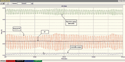
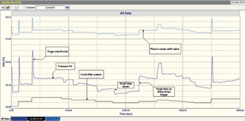
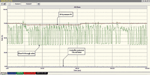
Figure 1 shows the operation of the loop, with a reasonable tuning, in closed loop (automatic). There was an additional flow transmitter in series with the pressure control valve and this flow PV is also shown in the recording. The control strategy used the pressure as the temperature secondary cascade, which is fine, as the pressure mirrored the flow very well. (Personally, I prefer using a flow signal as a cascade secondary.) The figure shows the loop in a completely unstable cycle.
Figure 2 shows an open loop (manual) test performed on the loop, and shows the controller output, and the pressure and flow PVs. This is a remarkable test as it shows how badly the valve was behaving. The following points are of extreme interest:
1. On nearly every step of PD (valve output) in the positive (opening) direction, the valve responded with a really massive overshoot (about five times bigger than the step).
2. On steps in the PD in the opposite negative (closing) direction it gave very small undershoots which recovered quite slowly.
3. On one reversal the valve moved in a small step in the one direction, and three times more in the opposite direction.
4. Near the end of the test, at about 188 seconds, the PD was being ramped down slowly to see what the valve did. It can be seen from both PV signals that the valve was in fact very sticky, and moved down in steps.
5. On the very last step of PD it can be seen that the valve overshot and then came back and started drifting back in the open direction.
One can conclude from all these problems that the valve behaviour is non-repeatable and is not doing what the controller demands. You cannot perform control with a valve that behaves like this. It is therefore absolutely essential that the valve be repaired or replaced before one can go ahead and tune to achieve satisfactory control.
Example 2
The second example is of an important pressure control that had a persistent small cycle, but which on occasion would go violently unstable. Many people had tried tuning this loop but could not stop the instability.
Figure 3 is a closed loop test (in automatic) with the existing tuning parameters. The figure shows not only the pressure’s PV, SP and PD (controller output) traces on the recording, but we also managed to find that a flow meter had been installed further down the line and we were able to record the flow PV as well.
The recording is one of the most remarkable I have ever seen, as it shows that the valve was operating at an average opening of about 0,8% based on the controller output values. The valve is hugely oversized, probably by as much as 40 times!
Valve rangeability figures – the ratio of maximum flows that can be controlled through a valve – are published by the valve manufacturers. Even really very good control valves have quite a limited rangeability, typically 300:1. Simple valves like butterfly valves are typically 50:1. However, for simplicity, a well-known rule of thumb among practitioners of instrumentation and control is that, under normal control conditions, control valves should always operate above 20% of opening. There are various reasons for this, including:
• In many valve installations, the differential pressure across the valve seat becomes very high when the valve is almost closed. This can, and often does, lead to instability, particularly if the valve positioner has insufficient power to deal with this force.
• It is almost impossible for the valve manufacturers to machine the valve seat components accurately enough to allow good smooth characteristics when the valve is very near fully closed.
• When very close to seat, the smallest movements of the PD onto the valve actuator, especially from noise coming through from the PV, can result in effective on/off action – which is what is happening in this case. This can clearly be seen from the cycle shown on the flow PV, which is effectively amplifying what the valve is doing.
The most remarkable thing about this control is that in spite of the valve operating in an absolutely impossible region, at less than 1% of opening and with the huge oversizing, the control manages to keep the PV pretty well at SP for most of the time. It is a testament to the manufacturers of the valve and to the mathematicians who originally came up with feedback control theory, that a pretty effective control was being obtained for most of the time.
The other almost unbelievable thing is that it has been running like this for years in the plant and nobody was aware that the valve was dramatically oversized. It once again illustrates the abysmal lack of knowledge of the practicalities of control and that so few people have been taught the practical side. Truly amazing!
About Michael Brown

Michael Brown is a specialist in control loop optimisation with many years of experience in process control instrumentation. His main activities are consulting, and teaching practical control loop analysis and optimisation. He gives training courses which can be held in clients’ plants, where students can have the added benefit of practising on live loops. His work takes him to plants all over South Africa and also to other countries. He can be contacted at Michael Brown Control Engineering cc,
| Email: | [email protected] |
| www: | www.controlloop.co.za |
| Articles: | More information and articles about Michael Brown Control Engineering |


© Technews Publishing (Pty) Ltd | All Rights Reserved
 printer friendly version