

Loadcells are a key component when it comes to ensuring that the manufacture of consumer goods, food and pharmaceuticals, amongst others, remains accurate and delivers consistent product quality and packaging.
In principle, loadcells are not complex devices, however they do require some special attention when being installed or maintained. Many of these requirements are common knowledge, yet get overlooked during installation and commissioning with direct impact on the accuracy and repeatability of readings from a loadcell system.
The aim of this article is not just to remind users about these, but in addition to question if changes made to the system over time have added any of these items as risk factors to the performance of the current system.
Are loadcells still the best choice for bulk vessel measurements?
Bulk vessel measuring systems have seen some dramatic changes in technology over the past two decades with the development of radar and ultrasonic level measurement devices with increasingly advanced algorithms. Let’s examine their requirements in two sets, the first is physical (mechanical) and the second, electrical.
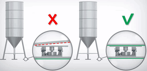
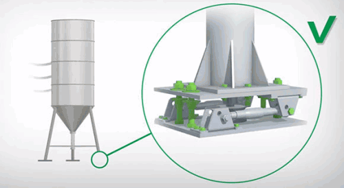
1. Support plates mounting to the loadcell need to be level or planar and the plates below and above the loadcell need to be co-planar as indicated in Figure 1.
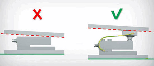
2. Mounting kits used should be suitable for both the loadcell and the application, and be able to compensate for any misalignment of support plates as indicated in Figure 2.
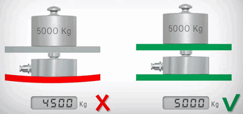
3. Support plates must be rigid and non-deformable as indicated in the example of Figure 3.
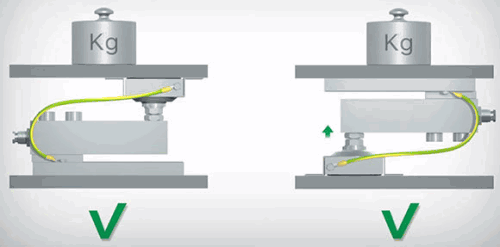
4. Pay attention to the load direction indicated on the loadcell body, and install accordingly. Remember that a loadcell can be installed ‘upside down’ as long as the load is applied in the indicated direct direction. Figure 4 indicates these two installation possibilities.
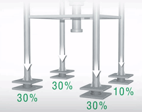
5. Remember that structures with 4 supports will not distribute the load uniformly and that 90% of the load can easily be distributed on just 3 of the legs. Keep this in mind when calculating the capacity of the loadcells as indicated in Figure 5.
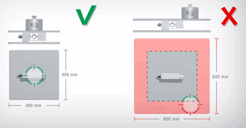
6. Preferably do not exceed 80% of the loadcell maximum rated capacity with respect to maximum load to be applied, or the designed load area, as indicated in Figure 6.
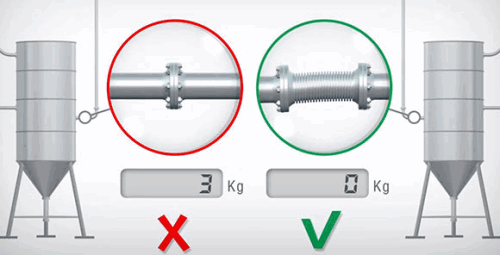
7. The freer a structure is the more accurate its readings can be. Make sure that any piping that is connected naturally aligns to the vessel so as not to add strain to it where it is not possible to use free couplings or flexible hoses, which are recommended to ensure free movement as indicated in Figures 7 and 8.
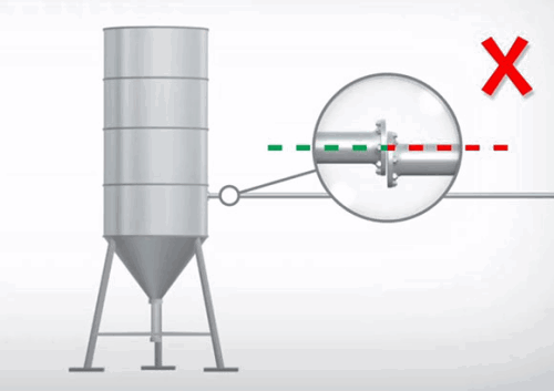
8. Pipe support structures on pipe sections directly connected to the measured vessel need to be located at least 40 times the diameter of the pipe away from the vessel as shown in Figure 9.
9. An easy test for correct mechanical installation is to zero the system after installation, apply a load of at least 20% of rated weight, remove the load and confirm that the value returns to zero. Repeat a few times to confirm stability.
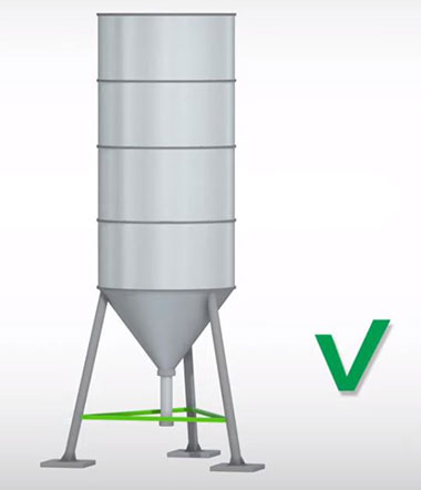
10. When using weighing systems with multiple loadcells, it is recommended to place constraints against both lateral and horizontal forces, which allows loadcells to operate correctly, avoiding potentially damaging stresses. In bulk vessels, examples include anti-tilt constraints as shown in Figure 10, and leg supports as indicated in Figure 11. Anti-tilt constraints in outdoor applications where accidental impact from moving vehicles can occur should also be considered, depending on the application environment. Structures with legs need these to be connected to each other or otherwise properly secured to prevent flexing under load, which can cause lateral force on the loadcells.
With all these preparation requirements, it is tempting to give preference to radar or ultrasonic sensors that require only a single hole at the top of the vessel and a few test measurements to get them up and running. In a future article, we will look into the electrical requirements and discuss the niche that loadcells have carved for themselves in the bulk measurement environment.
To learn more about weighing system developments, be sure to join the world’s largest weighing community online at Weighing Systems 4.0 on Linkedin.
*Images courtesy of Laumas
| Tel: | +27 31 702 5767 |
| Email: | [email protected] |
| www: | www.abacus-automation.co.za |
| Articles: | More information and articles about Abacus Automation |


© Technews Publishing (Pty) Ltd | All Rights Reserved
 printer friendly version