

Diagnostic characteristics play a major role in determining a machine’s availability and commissioning time. In addition to error detection, exact error localisation is important. EtherCAT has various different diagnostic features inherent to its system.
In EtherCAT networks the slave devices process the Ethernet frames according to the topology determined by the hardware using a dedicated real-time component, the so called ESC (EtherCAT Slave Controller). The slave devices come with diagnostic mechanisms on all layers of the ISO/OSI stack specified in the fieldbus standards. The progression of the status information from the individual slaves is carried out by the master, respectively the configuration tool, which reports directly to the application software, respectively the user.
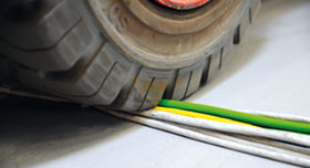
Diagnostics on the physical layer level
The physical layer includes cables and connectors for building the infrastructure of the network. Each ESC port monitors the communication on the hardware level by processing relevant information to the user. In addition to the different errors, ESC ports detect Link Lost occurrences and increment accordingly a Link Lost Counter. Such errors can be caused by loose contacts, insufficient connections or broken cables. By reading out the appropriate registers, the disturbance of the physical medium can be localised precisely.
Another diagnostic feature is the CRC check (check sum) of the incoming frames: In case of failure the corrupted frame is marked as damaged, the data contained therein is ignored and the CRC Error Counter is incremented. Following devices ignore the data of this frame, too, and increment a Forwarded CRC Error Counter instead. CRC errors are typically caused by EMC disturbances as they occur in energised cables, which run near to the communication cable. By reading out the register of both error counters the user can detect the location where possible EMC disturbances have interrupted the communication.
Diagnostics on data link layer level
The data link layer guarantees the data exchange between the EtherCAT frame and the EtherCAT participants in the network. This exchange can be both acyclic and cyclic. The latter can also be controlled cycle synchronously between several distributed participants. In the slave devices, interrupts or watchdogs monitor the data exchange and synchronisation.
A very powerful diagnostic mechanism on the data link layer level is the Working Counter, which is transferred with each read and write command. This counter increments after successful data exchange in each passed slave. By comparing the actual with the expected figures the master checks within the same cycle if all slaves work with consistent data or if individual datagrams have not been transmitted. The Working Counter informs about different possible errors, e.g. if a slave cannot exchange data due to missing connectivity or internal hardware interrupts. In addition, problems with parameterisation, which include the configur-ation of process data or the communication timing, are detected that way.
Working counter errors are processed to an overlaid application, e.g. a PLC program, so the applicator can code a suitable response in the software.
In applications that require a high grade of synchronicity of their components, the mechanism of distributed clocks is used within the EtherCAT network. For this data link layer functionality, there are different diagnostic mechanisms, too. Each slave includes a system time difference register, which contains the difference between the local clock in the slave and the global network time. By reading out this register value from all slaves which use distributed clocks, the master can monitor how precisely the network is synchronised and inform the user in case of irregularities.
Since EtherCAT uses standard Ethernet frames, the network status can be monitored via free-of-charge software tools, e.g. Wireshark. That way, whole EtherCAT frame as well as all datagrams within them can be analysed and displayed.
Diagnostics on application layer level
The application layer applies to the individual functionality of each slave: for example, reading a temperature signal, controlling pneumatic servo valves or driving a motor. Here, one source of significant diagnostic information is based on the EtherCAT State Machine, which organises the interaction between master and slaves. Each status corresponds with a number of available communication functionalities. Status changes are required by the master and confirmed or denied by the particular slaves. In case of configuration errors during start-up or internal runtime errors, the slave denies the status change or changes to a lower status internally, sets an error bit and provides an error code. An example for this diagnostic function is given when the process data configuration between master and slave differs: the slave will deny a status change to SafeOperational with the error code ‘Invalid Input Con-figuration’. Another example is given when the slave does not receive valid process data for a special amount of time: it then changes its status to SafeOperational and reports the error ‘Process Data Watchdog’. The application layer status registers can be read by the master with a single broadcast command, which monitors the complete network status.
Besides the central diagnostic ability via the EtherCAT State Machine, EtherCAT devices can report specific internal application errors. Those are dependent on the individual function of the slave: This can be an overvoltage for an analog input terminal, which exceeds the maximum torque limit for a drive, or an internal overheating alarm. CAN application protocol over EtherCAT (CoE), the standard EtherCAT protocol for the acyclic parameter access, defines the Diagnosis History Object, which works like an error register. Within this object, devices can record and save up to 250 application specific diagnostic messages, which can be read by the master and reported to the user.
Conclusion
Distinctive diagnostic functionality exists on all levels of EtherCAT communication and thus provides a full and detailed overview about the network status. This functionality inherent in the EtherCAT protocol can be centralised by the master, using a few additional commands. These diagnostic mechanisms are implemented in hardware as defined in the basic specification of EtherCAT: therefore, the support of all related functions is guaranteed for all EtherCAT devices similarly.
For more information contact EtherCAT Technology Group, +49 911 540 56 226, [email protected], www.ethercat.org


© Technews Publishing (Pty) Ltd | All Rights Reserved
 printer friendly version