

There are many obstacles to achieving satisfactory closed loop control of processes when process variables are sent to controllers over wireless. What are some of these obstacles and are they insurmountable?
Introduction
[In this article all references to wireless transmitters refer to battery-powered wireless instrumentation transmitters (such as battery powered wireless pressure transmitters) unless specifically stated. The term PID is used generically to refer to process loop controller algorithms that implement one or more of the terms P, I or D.]
The primary technical obstacles to implementing closed loop control, in which one or more of the communication links is wireless-based, are as follows:
* Battery life.
* Communication time delays.
* Variability in communication time delays.
* Loss of communication.
This article looks at each of these and tries to determine why these should be considered as obstacles, and at how they may be overcome. But first we need to touch on the nature of closed loop control and the PID (Proportional Integral Derivative) control algorithm.
PID control algorithm
PID basics
The goal of closed loop (feedback) control in industrial processes is to maintain a measured process variable (PV) at some constant value so that the process stream/end product of the process meets some desired standard.
The desired constant value is referred to as the set point (SP), and the difference between the measured PV and the SP is referred to as the error. In an ideal world the result of the PID calculation of the controller is a feedback signal to a final control element to adjust the final control element in such a way that the error signal is moved to zero.
PID time domain
The process response time comprises the process time constant plus the process delay. Different processes have very different process response times. Position control of one axis of a high-speed robotic handler positioning work pieces would typically have a very short time process response time, requiring the loop solution time to be in the order of microseconds. Whereas the level control loop of a valve maintaining level in a large holding tank might have a process response time in the order of minutes or even tens of minutes.
There is a rule of thumb that the loop solution interval of a controller should be between four to ten times shorter than the process response time of the process which the controller is controlling. That means that in order to maintain stable control of a loop with a process response time of ten seconds, the controller cycle time needs to be of the order of one to two seconds.
It is also important to note that the mathematical implementation of a standard PID block is reliant on a fixed loop solution interval.
Obstacles to wireless control
Battery life consequences
In practical terms wireless transmitters for closed loop control may need to be configured to operate at default update rates such as 15, 30 or 60 seconds.
With battery powered instrumentation, battery life is an important consideration that can have a significant and direct economic impact through maintenance costs and plant availability.
Industrial wireless technologies like ISA 100.11a1 and WirelessHART2 use two types of message initiation for reporting PV – periodic and event based.
When periodic transmission is configured, a scheduler in the transmitter periodically wakes up the transmitter which then forwards instantaneous PV information to its associated controller. The fixed time interval of the scheduler determines the default update rate (aka refresh rate) of the transmitter.
Event-based messaging relies on a scheduler in the transmitter that periodically wakes up the transmitter. The transmitter then samples the PV and if it is outside some defined range then that PV is forwarded to its controller.
Often both types of PV message initiation are configured in a transmitter so that there is a known maximum interval between new PV values being sent to the controller, even when the PV is stable and within the defined target range.
This apparent complexity is mandated by the need to maximise battery life. In an ideal world without battery life constraints, wireless transmitters for closed loop control would send data at least every second. But transmitting data is costly in terms of energy and mesh bandwidth and needs to be limited.
Communication time delays
Apart from the time impact of PV message initiation described above, there are other factors that introduce time delays in the complete transmitter-controller-final control element system. These delays are dependent on the selected system architecture.
Since we are talking of wireless transmitters, in most closed loop wireless implementations we can expect that in addition to the transmitter there will at least be a wireless gateway and there may also be a multi-hop wireless mesh to be traversed between the transmitter and gateway. Figures quoted by manufacturers1 estimate the delay between transmitter and gateway on to the plant backbone to be approximately one second for a direct hop and more where a mesh is involved.
Variability in communication time delays
The signal propagation time between the wireless transmitter and the control system backbone can vary.
This variation in the time taken for different PV measurements from the same transmitter to reach the controller is often referred to as jitter and may be caused by dropped packets, node failures and path recalculations in mesh networks.
Where loop final control elements are wireless, the output signal propagation between the control system backbone and a wireless final control element can vary for the same reasons.
Temporary loss of communication
Communication over wireless systems can be temporarily disrupted.
Node failures or RF interference may result in temporary breaks in the communications path between transmitter and controller, and between controller and wireless final control element.
Overcoming the obstacles
The solutions to the obstacles mentioned above can be classified as:
* Communication solutions.
* System architecture solutions.
* Mathematical solutions.
Communication solutions
There is a considerable amount of work being done in academia² to further improve wireless protocols in order to reduce the power consumption (and hence increase the battery life) of battery powered wireless instrument transmitters. While not all of this research relates directly to the industrial field, it can impact on future refinements of transmission power control level algorithms – in particular for applications where the wireless instrument transmitter is mobile and where there are transient interruptions to RF communications (for instance where transmitters are mounted on mobile devices, or where objects are moving between transmitter and gateway aerials).
The main thrust of this research is to arrive at real-time optimisation of wireless transmission power level. This is a trade-off between transmitting at a too high power level (and hence reducing battery life) and transmitting at a too low power level (which then results in dropped packets, more transmission retries and more power level negotiation messaging between transmitter and gateway, ultimately also reducing battery life).
If transmission power control can be further enhanced then for the same battery life, frequency of PV signal transmission can be increased.
System architecture solutions
System architecture solutions can address some of the obstacles described above. In general these solutions involve moving the transmitter, controller and final control element elements of the control loop closer together, thus reducing some of the time delays and jitter.
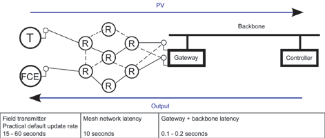
Worst case scenario
Figure 1 shows a worst case scenario for current state-of-the-art wireless system architecture. The system comprises a wireless transmitter routing PV data over a mesh network to a wireless gateway. The gateway then routes the PV via the control system backbone (typically Ethernet based) to a controller. The controller solves the PID control algorithm and routes the output via the backbone, gateway and mesh to the final control element, which then adjusts the process. As a result of transmitter scheduling (perhaps 15 seconds or above), wireless network latency (perhaps 10 seconds at best) and backbone/controller latency (of the order of 0.1 – 0.2 seconds) this solution would be considered unacceptable by most control engineers, except in the case of processes with very slow process response times.
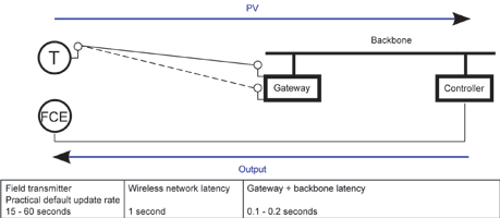
Slimming down
Figure 2 shows a more acceptable architecture, where the mesh topology of the wireless network has been replaced with a star topology for routing the PV directly from transmitter to gateway and where the final control element is hardwired to the controller. Eliminating the mesh partially addresses the objection of communication time delays and also the objection of variability in time delays since the route between transmitter and gateway is fixed and there is no possibility of dynamic recalculation of routing tables occurring. It does, however, mean that the redundant nature of mesh networks is lost for the PV.
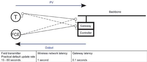
Moving closer
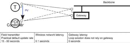
Figure 3 depicts a solution where the PID loop control algorithm is solved in the gateway itself. Effectively the PID controller is incorporated in the processing capability of the gateway. This helps to reduce some of the loop latency, but does not address jitter.
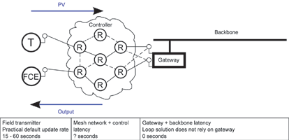
Virtual controller
The solution shown in Figure 4 is of an innovation that has been the subject of a considerable amount of academic research³ – that of the Wireless Control Network (WCN). In this architecture the controller is virtualised in the mesh network. It does not exist as a discrete entity in any one node of the mesh, but it can be considered as a swarm solution where a small portion of a feedback algorithm is solved in each node.
Such a solution partially addresses overall loop latency and jitter.
And closer still
There has been a movement over the last four or five years to move control into the field (control in the field or CIF). Figure 5 shows one possible variant of this, where a wireless transmitter passes a PV directly to a wireless final control element in which a loop controller is embedded.
Many wired field instruments (transmitters and final control elements) are now available with embedded controllers and this trend is being repeated with wireless devices. In May 2013, an ISA 100 Wireless product demonstration at Hannover Fair showcased wireless control in the field, in which an ISA 100 Wireless Yokogawa pressure transmitter communicated directly with an ISA 100 Wireless Flowserve smart valve positioned4.
And the good news for plant owners is that with the January 2014 Fieldbus Foundation announcement of the release of the final specification for integration of ISA100.11a wireless field devices into its Foundation for Remote Operations Management (ROM) technology5 , end users can look forward to employing multiple wired and wireless protocols for greater flexibility and expandability.
Mathematical solutions
No matter how close the controller is located to the transmitter, the fundamental problems remain:
* For acceptable battery life the wireless transmitter needs to send the PV to the controller far less frequently than in a hardwired solution.
* Wireless signal pathways will be subject to jitter.
* Wireless signal pathways will be subject to occasional loss of signal.
These obstacles mean that wireless solutions in closed loop control using classical PID controllers are at best a compromise, because for stable control without detuning, classical PID controllers:
* Need to solve the algorithm at a fixed interval with a new PV at a rate that is at least one order of magnitude faster than the process response time.
* Calculate the derivative and integral portion of the control at every periodic execution of the function block and use this fixed execution time in these calculations.
Consequently classical PID controllers cannot tolerate the lower rate at which wireless PVs are made available and cannot compensate for the aperiodic nature of the PVs (as a result of jitter or temporary loss of PV signal), without introducing process oscillations and disturbances, which lead to off specification streams or other costly process inefficiencies.
The development of suitable feedback and predictive controllers that can tolerate these challenging conditions is the subject of research in vendor organisations and academia and is the subject of several patents6.
At the time of writing, and after contacting several of the major process control vendors, the writer is only aware of one commercially available solution, Emerson’s PIDPlus7, which falls under this category.
Emerson PIDPlus
Emerson has developed; successfully field tested, patented and incorporated its PIDPlus algorithm into the DeltaV process control system.
Unlike classical PID, PIDPlus:
* Only calculates the integral and derivate contributions of its algorithm when new PV data is received, and uses the (variable) elapsed time interval between updates in its calculations.
* The loop reset calculation uses positive feedback based on the process response time to suppress process oscillations where the PV update rate is much slower than the process response time.
* Does not wind up its reset action when there is a loss of communication with the instrument transmitter or final control element.
For these reasons PIDPlus facilitates the use of wireless transmitters by successfully controlling closed loops where the process response time is faster than the update time.
Should you consider wireless closed loop control?
The use of wireless closed loop control should not be considered where processes can go out of control (endanger personnel, cause equipment damage, trigger shutdowns or produce off-specification product) within the interval of the wireless transmitter’s update rate.
Apart from the above no go applications, wireless closed loop control can be a viable alternative to wired closed loop control for applications such as flow control, hot well temperature control, vessel pressure control, level control and heat exchanger control.
Resources
Emerson: Web site http://tinyurl.com/n95ag9a
Honeywell: Web site https://honeywellprocess.com
ISA 100 Wireless: Web site http://isa100wci.org
WirelessHART: Web site http:// www.hartcomm.org
Yokogawa: Web site for field wireless http://tinyurl.com/ny2gwau
References
1. ISA 100 Wireless compliance institute; White paper: Control Over Wireless: Current Applications and Future Opportunities http://tinyurl.com/m7f8gmo
2. Dept. of Computer Science, Kyonggi University, Korea; Paper: A Study of Transmission Power Control Algorithms in Wireless Body Sensor Systems http://tinyurl.com/q2bectk
3. Dept. of Electrical & Systems Engineering, University of Pennsylvania, USA Paper: The Wireless Control Network: A New Approach for Control over Networks http://tinyurl.com/qx4usbf
4. ISA 100 Wireless; News release http://tinyurl.com/ltkua4x
5. Fieldbus Foundation; Remote Operations Management http://tinyurl.com/po4mpug
6. The US Patent and Trademark Office; US Patent Nos.7587252, 7620460,7945339 http://uspto.gov
7. Emerson White paper: DeltaV v11 PID Enhancement for Wireless http://tinyurl.com/oxbla3d

About the author
Andrew Ashton has electrical, mechanical and business qualifications and has been active in automation and process control since the early 1980s. Since 1991 he has headed up a company that has developed formulation management systems for the food, pharmaceutical and chemical manufacturing industries and manufacturing solutions involving the integration of various communication technologies and databases.
Developed systems address issues around traceability, systems integration, manufacturing efficiency and effectiveness. Andrew is a contributing editor for S A Instrumentation and Control.
| Tel: | +27 31 764 0593 |
| Email: | [email protected] |
| www: | www.technews.co.za |
| Articles: | More information and articles about Technews Publishing (SA Instrumentation & Control) |


© Technews Publishing (Pty) Ltd | All Rights Reserved
 printer friendly version