

Distributed in southern Africa by Dupleix Liquid Meters (DLM), Solartron Mobrey's Hydrastep is most often used as a rugged remote indication and level alarm/tripping device; however in certain situations the system may also be used to provide the measurement input to a control scheme for effective water level control.
Heater control schemes can be greatly simplified by using the device for level control as well as for the heater level alarms and trips. Hydrastep's fully redundant system provides level alarms and analog outputs for reliable and repeatable level measurement system. An update rate of 20 measurements per second allows for precision control even under demanding or emergency situations. With over 4000 installations worldwide, Hydrastep is industry proven and gives virtually maintenance free level measurement.
The stepped nature of Hydrastep is normally the primary concern when implementing such a control strategy. Reducing the spacing between electrodes and increasing the number of electrodes reduces the problems to some extent, however, further consideration of the control algorithm is needed in order to optimise the performance of the control system.
Control system definition
The control system consists of a measurement input, in this case, Hydrastep, which produces an analog (4 to 20 mA) signal representing water level. The analog signal is fed to a controller, either a local, standalone controller or a DCS system, which compares the measurement input with the desired level and produces a control output to decrease the error between the desired level (setpoint) and the measurement input (water level). Control is normally achieved using a 3-term (PID) controller or algorithm. Each of the three terms (Proportional, Integral and Derivative) has associated variables that alter the response of the control loop.
Where
m = control output
e = error from setpoint
kp = proportional gain (proportional band = 1/kp)
tI = integral time constant (reset time)
kI = integral gain
td = derivative time constant (rate time)
kd = derivative gain
Optimisation of the control loop
To get the best out of the control loop the disturbance to the control output caused by having the stepped measurement input needs to be minimised, particularly around the setpoint. This can be achieved by implementing P.I. control only strategy - in conjunction with gain scheduling (adaptive gain control). Gain scheduling allows the proportional gain term to vary as the error from setpoint changes. To minimise the stepped input effect the gain scheduling should be set such that there is very little or no proportional gain at or near the setpoint, but as the error from setpoint increases so does the proportional gain term. This implementation creates a control loop that is 'Integral only' at or near the setpoint, with proportional control being added as the error from setpoint increases beyond a set value so that fast corrective action is taken when necessary.
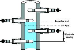
The setpoint should be fixed mid-way between two electrodes; this creates a situation where there is always an error from the setpoint. At or near the setpoint, the induced error causes the control loop to continually change the control output, at the rate and time determined by the integral time constant (reset time). As the water level increases and touches the electrode above the setpoint the error will be + (Electrode spacing)/2.
The control loop will respond by lowering the water level. As the water level drops below the electrode the error will be become - (Electrode spacing)/2, causing the control loop to increase the water level.
In practice the implementation described causes the water level to be controlled to a point just touching the electrode above the setpoint. In steady state situations with the water level at or near the setpoint the control output ramps slowly up and down at the time determined by the integral time constant (reset time) creating a smooth control output. If a disturbance in the level is introduced then the proportional gain term takes over and takes quick corrective action.
Experience has shown that the following set of values are a good starting point for setting up the control loop for most feed-water heater level control applications.
The actual values finally used will obviously depend on the installation; valve type and sizing etc, the above values are only given as a starting point guide.
For more information contact Dave Rosser, DLM, 011 457 0500, [email protected], www.dlm.co.za
| Tel: | +27 11 457 0500 |
| Email: | [email protected] |
| www: | www.dlm.co.za |
| Articles: | More information and articles about Dupleix Liquid Meters Flow Control (DLM) |


© Technews Publishing (Pty) Ltd | All Rights Reserved
 printer friendly version