

All intrinsically safe equipment relies for its safety integrity on being adequately electrically protected so that electrical overloads do not generate excessive heat or incendive sparks. This article concentrates on intrinsic safety, where there tends to be more emphasis on the requirements of electrical protection and earthing. This is largely because of historical background to the development of the technique but is justified to some extent because of the use of intrinsically safe equipment in the more hazardous location of Zone 0. The possibility of working on circuits without isolating them and the requirement that some monitoring equipment has to remain functional in the presence of major gas releases or catastrophic circumstances also leads to further concern.
The earthing of shunt diode safety barriers illustrates the fundamental requirements very well and hence is discussed in considerable detail. The shunt diode safety barrier was introduced to remove the necessity to certify complex safe-area equipment. It is designed to permit the normal operation of the circuit, and if a fault occurs within the safe-area equipment it should prevent the passage of a level of energy which can cause ignition or a level of power which can cause excessive temperature rise. A more detailed description of the operation of shunt diode barriers and also galvanic isolators is given in TP1113 'Shunt diode safety barriers and galvanic isolators - a critical comparison'.
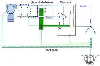
The protection technique of shunt diode barriers is illustrated by Figure 1. A fault current derived from the mains phase voltage invades the safe-area side of the barrier. Part of the current may flow through the fuse of the barrier, rupturing it; but a significant part of it would flow through the 0 V rail of the barrier system, being limited in magnitude only by the impedance of the fault circuit, and its duration determined by the fuse or other fault-current limitation protecting the phase providing the fault current. The return path provided to the neutral star point ensures that the fault current does not enter the hazardous area, by presenting a lower-impedance path along which the current prefers to flow.
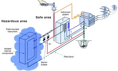
Barrier-protected intrinsically safe circuits are earthed at the barrier busbar only, and elsewhere are insulated from the plant structure. The field mounted instrument illustrated in Figure 1 would normally have its enclosure bonded to the structure and its internal electronics isolated from the case and directly connected to the barrier. (The level of isolation required is to be capable of withstanding a 500 V test. It is, however, advisable to avoid doing a 500 V test on an installation where there is any possibility of a flammable gas being present.)
During the short time that the fault current is flowing, a voltage drop occurs in the return path between the points X1 and X. This voltage difference is transferred to the field mounted instrument since the enclosure is bonded to the structure at the same potential as the point X and the internal electronics directly connected to the point X1. Since this voltage difference occurs in the hazardous area it is desirable that it should be less than 10 V so that the probability of an incendive spark is acceptably low. If the fault current from the 240 V supply is 100 A (a fault circuit impedance of 2,4 Ohm) then the impedance between X and X1 should be less than 0,1 Ohm. It is important to recognise that this is the resistance of the conductor between the barrier busbar and the neutral star point. The resistance of the connection to ground is not important since the fault current does not return to ground, it returns to the neutral star point. Various codes of practice suggests that a value of 1 Ohm is acceptable but this is possibly too high.
The lower value is usually readily achievable, since the barrier earth connection is always quite short and is a robust cable to ensure its mechanical integrity. For example, a 10 mm2 copper conductor has a resistance of 2,8 mOhm/m. Hence a 25 m cable would have a resistance of 70 mOhm and so would satisfy the requirement.
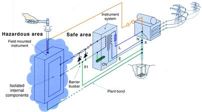
It is interesting that a mains supply fault in the hazardous area, as illustrated in Figure 2 produces a similar potential difference created by the fault current flowing through the plant structure. The multiple return paths and cross bonding must create a low resistance return path of the same order as the barrier earth conductor so as to avoid significant voltage differences.
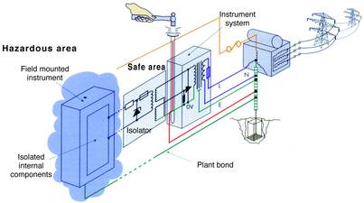
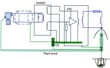
The use of galvanic isolators as interfaces changes the earthing requirements from being a primary contributor to the method of protection, to a secondary one. Figure 3 shows the fault being removed in a relatively short time by having a well-defined return path on the safe-area side of the isolator. Voltage elevation of the safe-area side of the isolator is not transferred to the hazardous area, but a prolonged mains fault would damage the components on the safe-area side, or more probably damage the computer input circuit. In these circumstances the earth return is not vital to safety and is primarily essential for operational and electrical protection reasons.
Combined earthing for interference avoidance and intrinsic safety purposes
In almost all circumstances the 0 V rail of the computer and the barrier busbar are linked by the method of measurement and hence the earth returns are combined.
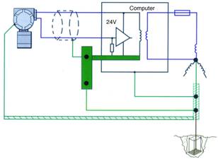
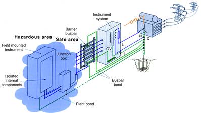
Figure 4 reiterates the normal practice of returning the computer 0 V and the screens of the field wiring separately from the structural and power system to the neutral star point. This system ensures a defined fault return path for any power faults or induced interference currents and prevents the power system currents generating a common mode voltage on the 0 V rail of the computer.
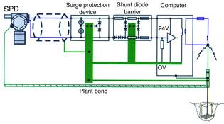
The introduction of the shunt diode barrier does not appreciably change the circumstances, as illustrated by Figure 5. The earth returns are combined by linking the computer 0 V rail and screens to the barrier busbar, and the earth return path should meet the resistance requirement of at least 1 Ohm but preferably 0,1 Ohm.
When isolators are used, the barrier busbar is omitted and the screens of the field wiring are connected to the 0 V rail of the system as indicated in Figure 6.
In these circumstances the earth return from the 0 V rail has to be of the same standard as for shunt diode safety barriers since the transient potential differences developed across it appear as voltage differences between the cable screens and the structure within the hazardous area.
Practical consideration
The conventional installation becomes as illustrated in Figure 8 with the barrier busbar and computer 0 V insulated from the structure and returned separately to the neutral star point bond.
It is normally a requirement that the barrier busbar return path be periodically checked. This check is much easier to do if the connection is duplicated as shown in Figures 8 and 9. If this is done then an accurate resistance measurement can be made by disconnecting one lead and inserting a low-voltage meter in series with the resulting loop. (Note that the loop resistance is four items the parallel resistance of the normal installation.) A record of this measurement should be maintained and any instability in the readings investigated. A great advantage is that such a check can be done without a major disturbance of plant function.
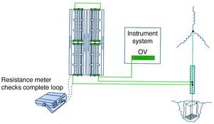
The two connecting wires need to be routed close to one another but should form an effective ring main as shown in Figure 9. Concern is frequently expressed about the resultant loop generating a magnetic pick-up problem but considerable experience suggests that this is not a practical problem. The earth return lead needs to be identified and a common practice is to bind the two leads together with blue insulating tape at frequent intervals so as to distinguish them from other similar conductors.
With this type of installation it is worthwhile to measure the resistance between the busbar and the cabinet, since this is an indication of the effectiveness of the structural bond. If facilities are available a note of the voltage waveform existing between the structure and busbar should be made. This waveform is frequently an indicator of deterioration in the structural bond or the introduction of interference-generating equipment. Frequently a knowledge of this waveform is useful in diagnosing problems.
Some care has to be taken that the terminals used for earth connections should be of high quality and vibration-proof. The best practical solution is to use the terminals that are suitable for increased safety (Ex e) installations. It is permissible to carry critical earth connections via plug and sockets, but three strategically placed pins must be used and some precautions taken to prevent disconnection without first removing power from the protected installation.
| Tel: | +27 10 055 7300/1 |
| Email: | [email protected] |
| www: | www.extech.co.za |
| Articles: | More information and articles about Extech Safety Systems |


© Technews Publishing (Pty) Ltd | All Rights Reserved
 printer friendly version