

Many operators are now considering mass flowmetering for bunker verification on receiving vessels, and for monitoring fuel consumption. However, to achieve accurate and useable measurement, the installation and the data being collected must be carefully considered. For bunkering, we must study the installation to improve filling and emptying and ensure all the relevant information from the meter system is collected. For fuel consumption measurement, there are significant advantages of mass flowmeters over mechanical metering, but again we have to ensure the meter is configured for the process and can be mounted in the harsh engine room environment. This article describes these considerations and provides advice on integrating the meters to deliver meaningful information.
Bunkering installations
There are principally two key areas of consideration for installation and specification of the bunkering measurement system.
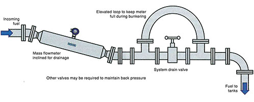
Firstly, how a meter should be installed so that it can fill quickly and can be fully drained on completion of the bunker stem to optimise measurement accuracy. Secondly, the data stored from the bunker stem [transfer of fuel] to ensure that historical quantities and the stem quality is held on record. Selection of an installation location is often restricted by the design of the vessel and the existing pipework routings; however this can compromise the measurement accuracy. The guidelines below should be followed and modifications made to meet them if required. During bunkering there is very little back pressure, therefore the bunker line is not always full. We need to install the metre to ensure the meter is full during the bunker process. On receiving vessels where the ranks are bottom filled it is easier to ensure the lines are full, but on top fill tanks the fuel falls under gravity and the lines are often partially filled. To resolve this issue, mounting the meter in a horizontal line lower than the main bunker line assists in ensuring the meter stays full during the majority of the bunker stem.
Mounting the mass flowmeter vertically with the flow from top to bottom required some restriction after the meter to ensure the meter stays full. In a situation with top filled tanks even this is not sufficient to ensure the meter stays full so horizontal installation is required as explained above. However, a second consideration must be made, to ensure the meter can be drained fully after the bunker is completed. Allowing heavy oil to remain in the measuring system even in very small quantities must not be allowed to occur; otherwise the meter will count ‘ghost’ measurements when no flow is present. Figure 1 shows an ideal installation for a straight tube mass flowmeter. The valve is opened at the end of the bunker stem to allow for the meter to fully drain; this is often assisted by air blown down the bunker lines.
Bunker stem data
Data acquisition and storage of the bunker stem data is critical. The main measurement is of course, the mass transferred during the bunker stem to allow comparison with the bunker note but other variables can be collected to compare with the bunker note and during the bunker cycle to show a complete picture of what happened during the bunker stem. The mass flowmeter is a multi-variable device and can provide multiple outputs of volume, density and temperature as well as mass. Using these to compare to the bunker note can assist in identifying the cause of differences between the bunker note and measured transfer data. Collecting data throughout the bunker stem can allow comparisons of bunkers to see the differences in variables available, such as the two-phase flow signal, which indicates the entrained air content on the bunker fuel being transferred. Collecting data is only the beginning, buying a meter system only gives data. That data must be represented and displayed in a way where it provides information which can be understood and acted on. To provide this functionality dedicated software visualisation tools are available which allow the engineer on the receiving vessel to see the bunker process as it happens and control the process and act when deviances or errors are seen.
Fuel consumption measurement
The primary advantage of mass flowmeters is that, even if the meter stops measuring, the flow of fuel to the engine can still continue. Using meters which have secondary containment ensures that even in the very rare event a measuring tube fails, the meter remains safe and fuel still flows to the engines. The engine room environment requires rugged and vibration-proof metering solutions, which can be installed easily below decks. Most mass flowmeters cannot be mounted directly on the meter body and meters must be suspended from the pipework. Krohne has developed a range of meters which can be clamped on the metre body so that the pipework is not supporting the meter. Mass flowmeters use a vibrating measuring system within the instrument. This measuring system must be isolated completely from the vibration of the working environment around them. Unfortunately many mass flowmeters available on the market are not sufficiently isolated to perform reliably in the engine room or require special installation to allow them to be used.
Marine fuel consumption systems often work on a differential measurement basis, the difference between the fuel return is deducted from the fuel feed measurement to determine the consumption. Unfortunately from experience we have seen that on many systems under some operating conditions the engine draws fuel from the feed and the return lines. Therefore we suggest that all mass flowmeters on fuel consumption systems are set up for bi-directional flow and the visualisation system shows this as totalised data and makes available the forward and reverse flow information for diagnosis purposes.
Krohne has also pioneered bulk transfer mass flowmeters with twin straight tubes suitable for bunkering applications which are far more compact than the traditional and cumbersome twin bent tube meters. This ease of installation and small installation envelope, combined with the natural viscosity insensitivity of the innovative straight tube design, coupled with the synthesised drive will deliver mass flowmeters for bunkering which provide the operator with continuous direct and accurate measurement of the bunker stem.
For more information contact John Alexander, Krohne SA, +27 (0)11 314 1391, [email protected], www.krohne.com
| Tel: | +27 11 314 1391 |
| Email: | [email protected] |
| www: | www.za.krohne.com |
| Articles: | More information and articles about KROHNE |


© Technews Publishing (Pty) Ltd | All Rights Reserved
 printer friendly version