

Emergent wireless technologies have created a lot of excitement in the control and instrumentation world. Many different wireless solutions are offering new ways to solve traditional industrial communication problems beyond simple cable replacement. Instrumentation engineers are encountering wireless more frequently e.g. field sensors, PLC and scada connectivity via wireless are becoming commonplace. Therefore, a good basic understanding of wireless technology is essential to enjoy success with it. One critical, but often overlooked, component of wireless building blocks is antennas. Despite the vast strides made in wireless technology, antenna basics remain the same.
How antennas work
Antennas come in various shapes and sizes which essentially determine their overall performance. Most importantly, the desired operating frequency has a direct influence on the design: in general, the higher the frequency, the smaller the antenna, governed by the following formula: Wavelength (m) = 300/frequency (MHz). For a radio operating at 2,4 GHz, the wavelength is 12,5 cm. Most common antennas are designed to be ¼ or ½ the wavelength of the radio signal for practical purposes. The antenna in this example would typically be around 3-6,5 cm in length.
Antenna Terminology
Antennas are characterised by various parameters. The section below covers some of the most common found in the manufacturers' data sheets.
Frequency and bandwidth
The frequency for which the antenna was designed is usually given as a range e.g. 2,38-2,52 GHz. While a mismatch of antenna to system frequency may still allow some absorption of the waveform, its relative efficiency and reliability is greatly reduced. For practical reasons, ensure the frequency of the radio system used is within the antenna’s capability.
Gain
Antennas do not create power; they simply focus the radiated RF into narrower patterns. This makes it appear as if more power is coming from the antenna in the required direction. Antenna gain may be expressed as either dBi (with reference to an isotropic antenna) or dBd (with reference to a dipole antenna). This can be confusing as manufacturers do not always specify which metric is referenced. The thing to keep in mind is an antenna increases the gain of the overall system. Radio regulations stipulate the limit on the maximum transmitted power, which includes additional gain as a result of the antenna.
Polarisation
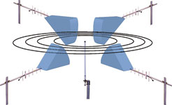
The two main types of polarisation encountered on industrial wireless antennas today, are vertical and horizontal. Most dipole and collinear antennas are vertically polarised i.e. they need to be mounted vertically. A Yagi antenna is polarised too and needs to be oriented correctly for optimal performance. The antennas in Figure 1 are vertically polarised, both the Yagi’s and the central omni-directional dipole antenna.
Voltage Standing Wave Ratio (VSWR)
VSWR is often given on antenna specifications sheets and is a measure of antenna efficiency. In an ideal world the VSWR of 1:1 which means that no power is reflected back to the source i.e. a perfect (impedance) match and all transmitted energy radiates out of the antenna. In reality however a VSWR of 2:1 or better is not uncommon and considered sufficient.
The smaller the VSWR the better the antenna is matched to the radios transmission line and the more power is delivered to the antenna. A 1.5:1 VSWR results in a 4% loss in power and 2:1 represents an 11% loss, still acceptable depending on the application and range required.
Rated power
To ensure reliable operation, make sure that the rated power of the antenna is not exceeded by the radio’s transmission power.
Antenna types
Simplistically antenna can be divided into two categories: omni-directional and directional – Figure 2 refers.
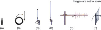
Omni-directional antennas have an approximate 360° horizontal radiation pattern i.e. they attempt to radiate equally in all directions around the antenna. Small omni-directional antennas, often called ‘whip’ antennas (Figure 2 A & B) are typically used for short range communications, e.g. wireless sensor networks, and often connected straight onto the radio device.
Two types of physically larger omni-directional antennas are known as dipole and collinear (Figure 2 C & D). These are normally connected to a radio device via a length of coaxial cable and are generally characterised by higher gain. A collinear antenna is essentially multiple dipole elements connected together for additional gain. Collinear antennas are normally manufactured with gains of 5, 8 or 10 dB. Like dipoles, collinear antennas are vertically polarised.
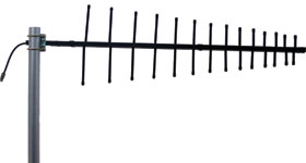
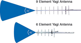
Yagi antennas (Figure 2E) are an example of directional antennas. As an analogy, an omni-directional antenna radiates like a light bulb, whereas the Yagi radiates as a torch. The strength and shape of its radiation is defined by its gain (Figure 3). The higher the gain, the more focused the forward radiated waveform. Consequently, the back and side lobes are reduced. Yagi antennas can be either vertical (more common) or horizontally polarised, depending on the orientation of the elements relative to the earth’s surface (vertical elements means vertically polarised).
Installation
It’s often tempting to mount antennas in the most aesthetically pleasing way, but this is not always the optimal from an RF point of view. Dipole and collinear antennas provide optimal performance when installed a minimum of 1-2 wavelengths clear of walls or steelwork. e.g. for a 2,4 GHz antenna system, a minimum clearance distance of 12,5 cm is desirable. When mounting Yagis, or directional antennas in general, it is important to keep polarisation in mind e.g. if a transmitting omni-directional antenna is vertically polarised, the receiving Yagi antenna must be vertically polarised as well.
A common problem with wireless systems is created when antennas are mounted in close proximity to each other. This is applicable even if the other antenna is on a different radio band, as the high RF energy emitted from nearby can ‘deafen’ the receiver. Physical antenna separation is therefore important and the separation distance needed depends on the frequency of operation as well as the relative RF power.
Lastly, care must be taken when mounting an antenna inside an enclosure. If a metallic enclosure is used, most of the radiated RF energy may be absorbed before it propagates to the outside, on the other hand, non-metallic enclosures have little blocking effect on the RF signal.
Summary
Antennas are a critical but often overlooked component of a wireless communication system. Although they appear to be simple, there is a fair amount of complexity in understanding their operation. For practical purposes, a basic antenna understanding, coupled with the antenna installation guide, is needed for instrumentation and control engineers in order to use them effectively in an everyday industrial application.
For more information contact Tabateq, +27 (0)21 762 8995, [email protected], www.tabateq.com


© Technews Publishing (Pty) Ltd | All Rights Reserved
 printer friendly version