

Part 1 featured in SA Instrumentation and Control March 2010.
System considerations
AA: OK, so we know our environment is Zone 0, we are working with a gas that will be safe with equipment rated IIC T4, we have selected ‘ia’ as a suitable protection technique. The loop equipment comprises components classified as simple apparatus and we have a pretty good idea of what the loop will look like. What comes next?
JA: This is probably a good time to start documenting the loop, even if some details like exact model numbers are missing. An important part of the loop document is indicating the zones into which each piece of apparatus will be installed. The goal is to install as little equipment as possible in the higher risk zones. So in our example we have only the RTD in Zone 0; the temperature transmitter in Zone 1; and the rest of the equipment in a non-hazardous area. (See Figure 1.)
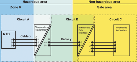
We are going to need the final drawing for loop approval as required by South African legislation, and subsequently for installation and maintenance.
Interface/Transmitter
AA: Are designers free to mix and match any suitably rated equipment in an intrinsically safe (IS) loop?
GF: I guess that depends what you mean by ‘suitably rated’. An IS loop is a system and the overall safety of the loop is dependent on the mutual compatibility of each piece of equipment in the loop.
It all starts with how much energy you supply to the loop, so for this stage of the design process we need to consider the intrinsically safe interface which is installed in the non-hazardous area and the temperature transmitter that is connected to the interface.
JA: For this exercise designers need to have the data sheets for the proposed IS interface and temperature transmitter available, and they need to ensure that the vendor has a valid IA certificate for the interface or else the loop will not get approval.
Firstly, we compare the levels of protection, gas grouping and temperature classification for each of the devices. The combination of two devices of differing ratings will require the lowest rating of the two to be used. So if the devices are rated Ex ia IIC T2 and Ex ib IIC T4 then the combination may only be used for Ex ib IIC T2 or less sensitive applications.
The next step is to consider the electrical interface between the IS interface and the TT. The spec sheet will show the maximum input parameters (voltage Ui, current Ii and power Pi) allowable. These must be compared with the output parameters of the interface (Uo, Io, Po). The devices are only compatible of the output parameters of the interface and less than or equal to the input parameters of the TT.
AA: How are the effects of cable capacitance and inductance taken into consideration?
JA: Generally these effects only impact design when cables exceed 400 metres, in systems installed in Zones 0 and 1, where IIC gases (hydrogen) are the source of risk. But for completeness we can describe the calculation for readers.
The permitted capacitance of the cable (Cc) is calculated as the permitted output capacitance of the power source (IS interface) (Co) less the input capacitance of the field device (TT) (Ci).
The permitted cable inductance (Lc) is calculated in a similar manner.
If the input inductance (Li) and capacitance (Ci) of the field device are negligible compared with the output (o and Co) of the supply then with these two results, the permitted L/R ratio of the cable can be calculated. If the input parameters exceed 1% of the respective output values then things become more complicated and I refer readers to IEC 60079-26.
In practice the designer knows the cable characteristics and will calculate the maximum allowable length of the selected cable that can be used based on Cc and Lc and will then annotate the loop with that permitted maximum length. This prevents the need to request a new approval if the length of cable is changed but remains within the calculated maximum.
We also need to ensure that the level of insulation from earth is acceptable or that specified system earthing requirements are met.
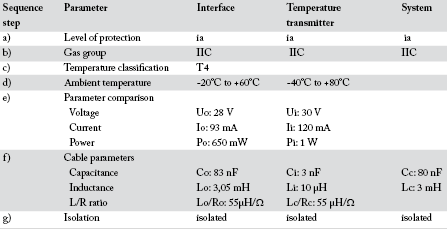
If all of the above criteria are satisfied then we can say that this part of the loop meets the IS requirements. This analysis should be documented. (See Table 1.)
Transmitter/Instrument
AA: How does the fact that the RTD is a simple apparatus and will influence the IS loop design?
JA: By its nature, a simple apparatus can be added to an IS loop without needing to recalculate the safety of the loop. We do still need to ensure that the RTD meets the gas group and temperature classification requirements. In this instance an IIC group is suitable for butane’s IIA gas group.
For the selected TT the Po is 2,5 mW, which is well below the 25 mW considered negligible for simple apparatus. This low power is incapable of raising the temperature of the instrument. Essentially this means that the maximum temperature that the TT will attain is the temperature of the process gas, which must be below its ignition temperature for a viable process design!
So in this instance we just need to consider cable specifications and earthing. The permissible cable specifications are calculated as previously. Because the RTD insulation specification is below 500 V, this part of the loop is considered earthed. This is acceptable because the TT is isolated and so no earth path is provided by the loop.
Broadly speaking that concludes the process; however, applications with high ambient temperatures will require further consideration.
AA: So all that is left is to fully document this with model numbers, terminal data and cable details and we are ready to submit to an ATL for loop approval?
JA: Designers should remember to include copies of the Ex certificates with their loop certification submissions.
Readers can find a copy of MTL document AN9003: A Users Guide to Intrinsic Safety at www.instrumentation.co.za/+C13571
About Dr Johannes Auret
Johannes Auret holds an MSc in Physics and a PhD in Engineering.
He started his working career at the CSIR and became involved in explosion prevention in 1993 when he joined the South African Bureau of Standards (SABS). At SABS he was promoted to manager of Explosion Prevention Technology and Rotating Machines. In 2001, he entered the private sector by joining Explolabs as co-owner and director.
Johannes has managed the SABS and Explolabs laboratories where explosion protected equipment is tested and certified. He also helps to manage the product certification scheme for explosion protected equipment operated by CERTEX. He also participates in standards development and has convened various working groups such as for SANS 10108 and ARP 0108, the key national documents on explosion prevention. He has served as the national representative for IEC Technical Committee 31 (explosion prevention).
Johannes is now in charge of Explolabs Consulting where he and his colleagues offer a range of explosion prevention services besides the obvious link to testing and certification, including:
* Area classification.
* Inspection of new or in-service Ex equipment & installations.
* Management system for Ex installations.
* Training courses, presentations and workshops.
About the author
Andrew Ashton has electrical, mechanical and business qualifications and has been active in automation and process control since the early 1980s. Since 1991 he has headed up a company that has developed formulation management systems for the food, pharmaceutical and chemical manufacturing industries and manufacturing solutions involving the integration of various communication technologies and databases. Developed systems address issues around traceability, systems integration, manufacturing efficiency and effectiveness. Andrew is features editor for SA Instrumentation and Control and editor of Motion Control in Southern Africa.
For more information contact Gary Friend, Extech Safety Systems, +27 (0)11 791 6000, [email protected], www.extech.co.za or Dr Johannes Auret, Explolabs, +27 (0)11 316 4601, [email protected], www.explolabs.co.za
| Tel: | +27 10 055 7300/1 |
| Email: | [email protected] |
| www: | www.extech.co.za |
| Articles: | More information and articles about Extech Safety Systems |


© Technews Publishing (Pty) Ltd | All Rights Reserved
 printer friendly version