

Challenged by John Deere, V I Engineering designed and developed a machine vision system that counts and measures falling objects smaller than 1 mm at more than 450 objects per second. The system measures time and XY position of each object as it is falling through a sensing plane. Line scan cameras and back illumination units are used in the system. Special algorithms were developed to distinguish objects in a clump.
There is a strong demand for systems that accurately measure counts, times, and positions of objects falling at high speed and at high rates in industries that make ball bearings, chemical pellets, seeds, pharmaceuticals, and other products. Such systems can serve as tools to improve manufacturing processes, as well as quality control in these industries.
Previously developed techniques such as grease belt systems and LED or photo-detector grids have been used to measure the distribution of falling objects. The limitation of grease belt techniques is that they do not take realtime measurements and they require extensive post-measurement processing. Addressing the limitations of the grease belt technique, the LED or photodetector grid provides realtime, high-speed measurement, but suffers some critical shortcomings, such as poor spatial resolution which restricts use of the technology to measuring objects larger than 4 mm. This technique is also unable to resolve multiple objects when they appear too close to each other as a clump.
A machine vision-based system using one line scan camera demonstrated better results than the grease belt and LED or photodetector grid methods, but the one-camera design did not solve the problem of distinguishing object clumps, or multiple objects that are too close and appear to be one object.
Vision system design
V I Engineering designed a machine vision system based on two line scan cameras and two linear backlighting units. One camera and one back illumination light are centred on the region of interest, or the area the objects fall through. Another camera and backlight pair is oriented perpendicular to the first set. It is aligned so that the scan lines of both cameras and the centre lines of backlights are in a same plane.
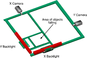
With the backlighting, each falling object appears as a black particle in a white background regardless of surface condition, brightness, and colour of the falling object. This means the vision algorithm does not need to be adjusted according to the appearance of the different objects. Two identical pairs of camera and backlight are orthogonally placed, so that with a specially designed algorithm they can measure the XY coordinates of the objects when they fall through the image plane. The image plane is a virtual plane that is constructed by the two cameras' sensor lines and the linear backlights when they are properly aligned. A purpose-designed alignment fixture is used to align the camera sensor line's position and angle so that the line scan sensors and the two linear backlights are aligned in a single image plane. The orthogonally oriented cameras provide another advantage over the one-camera configuration in that it allows the software to distinguish clump objects. When multiple objects are very close spatially, they may appear as one single object in one camera image. However, from a perpendicular angle, the other camera most likely sees these objects as separate particles in the image. With a specially designed algorithm, the system is able to match and identify all the objects in two images and separate the clumped objects.
Two IEEE 1394 line scan cameras with a resolution of 1024 pixels were selected for this application. Matched with two linear lights manufactured the cameras provide object resolution of better than 1 mm in a 150 mm x 150 mm image area where all the falling objects are measured. The bright backlighting creates a challenge when detecting smaller objects since they may not appear dark enough in the image due to an edge diffraction effect that reduces the contrast of the small object. To overcome this, the threshold value for smaller objects was adjusted and the system was then able to measure objects 1 mm or less in diameter.
The synchronisation of the two cameras is critical to accurately counting and measuring falling objects. The cameras are externally triggered using a pulse train signal from an NI PCI-6601 counter/timer card. With this single-source triggering of the scanning lines and the precise physical alignment of the two cameras, an object appears in both camera images at the same vertical position.
One PC was used to acquire images, process images, and run an object classification algorithm, as well as to display, generate, and report results. A NI PCI-8252 IEEE 1394 interface card plugs in to the PC and connects the two line scan cameras.
Calibration
The budget constraint of the project prevented the use of telecentric lenses for the cameras. Instead, low-cost machine vision lenses were used in the system. Due to the system's space limitation the camera lens was close to the inspection region, causing the images from the cameras to appear severely distorted. The main sources of this distortion are lens distortion at the edge of the field of view, and the perspective error of the lens due to the lens' proximity to the objects. The lens distortion causes an object's image to change size and shape when it is closer to the edge. The perspective error causes an image to change size when the object is at a different distance from the lens. Both distortions can cause time and position measurement error and a miscount of falling objects.
To overcome these distortions a novel calibration method was developed using a calibration target to mimic a calibration grid. A thin cylindrical target is placed and moved in a uniformly distanced grid map. Images are acquired and the positions of the target in both cameras are measured when the target is in each position. This yields a field calibration map that is basically a distorted grid image. The calibration function in the NI vision library was then used to convert all images to a uniform, undistorted image. All pixels are converted to real-world coordinates that are in millimetres. The size of the object in the image is also calibrated against its distance from the lens. After the calibration process, all objects' coordinates and sizes are corrected in the measurement result.
Clump objects
When a large number of objects fall at a high rate, some objects may appear as one clump. The two-camera approach largely overcomes this. Two or more objects which appear connected in one camera image will most likely show up as separate individual objects in the image from another camera that looks from a perpendicular angle. By counting and crosschecking the objects between the two camera images at the same vertical locations in the synchronised images, the algorithm can identify and distinguish objects in clumps. In rare situations that multiple objects appear in both cameras as a single object, the clump has a larger size, and the number of objects can be approximated from the size of the clump. Because this situation has a very low probability of happening, the approximation has proven to have little effect on counting accuracy.
System performance
Spatial resolution and accuracy
The spatial resolution of the system is determined by camera resolution, lens quality, lighting condition, scanning rate, and the physical dimension of the field of view. The camera selected for this application has a resolution of 1024 pixels. It covers more than a 150 mm field of view. Each pixel covers about 150 micrometres, which equates to a spatial resolution of 150 micrometres. 1 mm ball bearings were used to test the minimum detectable object size of the system. The system can easily count and measure these ball bearings.
Time resolution and accuracy
The time resolution of the system is determined by the line scan rate of the camera and the speed of the image processing. In this system, the camera has a maximum line rate of 10 kHz, which translates to 100 microseconds of time spacing between scan lines. Using different line scan cameras available in the market that have faster line scan rates, the time resolution of the system could easily be improved.
Because the cameras' line scan is triggered by an external precision pulse signal, the accuracy of the object timing measurement is mainly determined by the time resolution of that pulse. It is estimated to be 200 microseconds.
Counting accuracy
With the selected equipment the system is able to count objects with variable sizes at up to 450 objects per second with 99% accuracy. At the rate lower than 200 objects per second, the system has 99,5% counting accuracy.
For more information contact National Instruments South Africa, 0800 203 199, [email protected], www.ni.com


© Technews Publishing (Pty) Ltd | All Rights Reserved
 printer friendly version