

This article describes a pressure transmitter which offers built-in dynamic compensation for many of the errors and inaccuracies that can occur in differential pressure-based flow measurements.
One of the most common ways of calculating volumetric or mass flow is to measure the differential pressure (DP) across a primary element such as an orifice plate or Pitot tube. However, using only one instrument, the pressure and density (and hence flowing density) have to be assumed as constant in order to convert the DP value to a flow rate.
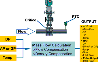
The DPharp EJX910A multivariable pressure transmitter from Yokogawa, in combination with its primary element, forms a flowmeter that computes standard volumetric or mass flow from measured differential pressure (DP) and flowing density using actual measured pressure and temperature.
Error sources affecting DP flow measurement
Figure 1 shows the measurement set-up. The basic mass flow equation performed is: Qm≈k.√(DP.P/T).
In DP flow measurements there are several potential error sources. These include:
* Primary element effects.
* DP measurement accuracy.
* Pressure and temperature fluctuations (variation in flowing density).
Primary element effects
The orifice plate is the most widely used primary element, and its accuracy is extensively debated. It is known, however, that its accuracy degrades over time as the plate loses its sharpness. A typical accuracy figure might be 1% of rate.
DP measurement accuracy
The accuracy of the DP transmitter is expressed as percentage of upper range value (URV), and is magnified by the square-law relationship between flow and differential pressure. Traditionally, DP-based flowmeters have featured a 3:1 turndown. Turndown is a figure that expresses the range over which the accuracy is perceived to be acceptable: 30-100% of flow for a 3:1 turndown.
If the accuracy of the DP transmitter is assumed to be ±0,2% URV, at 100% flow the accuracy is ±0,2% plus the error of the plate. At 70% flow (49% DP due to the square-law relationship), the accuracy would be ±0,4%; at 50% flow (25% DP) it would be ±0,8%; and at 25% flow (6,25% DP) it would be ±3,2%. The plate adds ±1% over the full range and, when ±2,5% total accuracy is perceived to be acceptable, that accuracy is reached at around 30% flow - hence the 3:1 turndown. Turndown is often increased to 9:1 by using two DP transmitters over the same plate with different ranges, a switching mechanism and a flow computing function. Today, of course, DP transmitters are much more accurate than ±0,2%. However, the accuracy is still expressed as a percentage of URV, and the square-law relationship between flow and DP is still applicable. Nevertheless, one could argue that a turndown of better than 5:1 is not normally achieved.
Pressure and temperature fluctuations
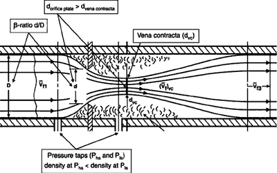
The error due to pressure (±0,5 bar) and temperature fluctuations (±10°C) in gas or steam flows can easily be of the order of magnitude of ±2%. The flow factor k in the basic formula above is a constant compensating for the differences between theory and real life. It is calculated as part of the orifice calculation, and is valid only for one particular set of operating conditions - making it another potential source of error. It is dependent on the discharge coefficient, the gas expansion factor and velocity of approach factor. The result of an orifice calculation is the diameter of the hole in relation to the pipe diameter: the so-called β-ratio. When a fluid is flowing through a pipe with an orifice plate, the flowing area reduction is abrupt, causing the smallest flowing area (Vena contracta) to be downstream (behind) of the plate. The discharge coefficient (based upon experimental research) compensates for the difference between theory and real life. However, the discharge coefficient is flow profile (Reynolds) dependent and varies with the flow velocity, pipe internal diameter, flowing density and flowing viscosity. In their turn, the latter three parameters are affected by flowing temperature. When a gas or steam flow passes the orifice plate (Figure 2), it is compressed upstream of the plate due to the obstruction caused by the plate. Downstream of the plate it expands again. The gas expansion factor corrects for density differences between the pressure taps, and it depends on the β-ratio, the isentropic coefficient (correcting for theoretical versus real-life expansion), differential pressure and static pressure. Again, temperature is having an effect as well. Finally, the velocity of approach factor is dependent on the β-ratio (d/D), which in turn is dependent on temperature. Pipe and orifice plate material expands or contracts as temperature changes, and the velocity of approach factor corrects for changes in β-ratio due to temperature fluctuation.
Dynamic compensation
The error in flow factor k increases with decreasing flow rate, significantly contributing to the overall flowmeter accuracy. A primary element of a DP-based flowmeter is sized for one particular set of operating conditions.
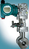
When in real life the conditions change - lower pressure, higher temperature, lower flow rate etc, - the user would like to re-calculate the flow-rate/DP relationship for every new set of conditions. This is exactly what the DPharp EJX910A multivariable transmitter (Figure 3) is able to do. It corrects for pressure and temperature variations and can compensate continuously for the effects of changing operating conditions on the flow factor. Using its flow configuration wizard, the multivariable transmitter can be set up to act as a flow computing device.
There are two options: basic mode and auto compensation mode. In basic mode, the transmitter only compensates for pressure and temperature fluctuations with a constant flow factor, in much the same way as a standard DP transmitter with a separate flow computer, resulting in a turndown of perhaps 5:1. However, in the auto compensation mode, the transmitter dynamically compensates for fluctuating conditions and their effects on the flow factor, reducing the error basically to the uncertainty intrinsic to the primary element. Consequently, the accuracy specification of ±1% of flow rate (assuming the primary element to be ideal) over 10:1 turndown in flow terms (equalling 100:1 turndown in DP terms) is only valid in the auto compensation mode.
Conclusion
The multivariable transmitter breathes new life into existing square-law flow measurements and, with its 10:1 turndown, not only eliminates the need for a separate flow computer, but can replace two DP transmitters over the same plate - achieving good performance over a wide flow range.
| Tel: | +27 11 831 6300 |
| Email: | [email protected] |
| www: | www.yokogawa.com/za |
| Articles: | More information and articles about Yokogawa South Africa |


© Technews Publishing (Pty) Ltd | All Rights Reserved
 printer friendly version