Process valves, sometimes also addressed as final elements are in many cases the most decisive factor when it comes to calculating the SIL level for a safety instrumented function (SIF). Due to the large variety of conditions of usage in the process industry there is a lack of appropriate data and approved devices.
Testing procedures like partial stroke testing can provide enhanced diagnostic coverage and therefore help to get improved reliability data for the total loop. Verification of this 'diagnostic data' and proper integration of these procedures into the safety instrumented system (SIS) and basic process control system (BPCS) environment at the same time poses a challenge.
New developments on actors and relevant approvals are presented as well as instrumentation with new functionality to support diagnostic coverage, different topologies for connection to SIS and BPCS are discussed.
Certified valves
Application of IEC 61508 in the process industry is now mandatory. Based on an analysis of possible hazards and risks, safety measures have to be defined and implemented with the goal to bring the risk down to an acceptable level. SIF are implemented to counter individual hazards. These SIFs typically comprise a sensor, monitoring the state of the process, a deciding logic, responsible for triggering the required action and a final element, blocking a pipeline or venting it, comprising a valve, an actuator and a solenoid valve. A quantitative analysis of the whole loop is mandatory. The reliability performance of the loop can be calculated based on the performance and reliability data of the single components. Therefore, manufacturers are increasingly getting more requests to provide reliability data, mainly the so-called dangerous failure rate, divided into detected and undetected failures and the safe failure fraction.
It is generally assumed that the performance of a typical loop is dominated by actuator and valve performance. The best numbers and therefore the least risk is created by the logic solver, followed by the sensor/transmitter element. The actuator/valve combination is rated worst. This might be astonishing at first glance, as a logic solver incorporating many electronic parts and even software seems to be more sophisticated and therefore more prone to error than the few pieces of metal making up a valve or actuator. However, the problem comes from the interaction with the process. Logic solvers, as complicated as they are, have been evaluated for a long time as being reliable as all the components and subsystems have a known performance. The key to success of this research, however, is that the logic solver operates in a known environment, the control room. In contrast, the final element is exposed not only to the environment, but also to the process. Due to the huge variety of materials, processes, phase states and other conditions that can be found in a chemical plant, it is very hard to gather enough data for making a sound statistical statement for a given material or substance or process.
If someone uses, for example, the well-known EXIDA library to check out instrumentation for his loop, he will find plenty of equipment within the categories of logic solvers and transmitters, also for barriers. But the valve section is much less populated, only three manufacturers and three valve types are listed, under which only the SAMSON valve is an instrument for general service. Checking into the performance level of the rated product, the valve series 3241 gives surprising figures of reliability. What is the background of these figures, can they be relied upon?
IEC 61508 opens two ways for defining reliability data: FMEDA or 'prior use'. FMEDA is the analysis of the design to calculate reliability data. But, as the use in the process industry can lead to process conditions and problems not foreseen, the second approach of using 'prior use' data seems to be more favourable. Prior use calls for recording and subsequent analysis of all failures for a given population in the field. There are also stringent requirements on the hours in use, which call for a large sample under investigation. To ensure both at the same time, large population as well as complete and comprehensive records on all failures is not easy to achieve. To address this issue, SAMSON AG together with Infraserv (former Hoechst AG) has run an investigation at their site in Frankfurt in a long-term project that seems to be the most comprehensive study on the market.
Noteworthy points are:
* Long period of six years for the investigation (1996-2002).
* A large quantity of around 40 000 valves used on site at the former Hoechst AG (operating hours) were under survey.
* Through German legislation (Gefahrgutverordnung) as well as through the internal guidelines of Hoechst AG, it was assured that all field failures were channelled through the central valve workshop.
* Complete documentation and fault analysis. A special questionnaire was developed in order to categorise failures. Special training of the personnel involved ensuring that all failures were correctly and consistently recorded.
* A decontamination room was set up for the purpose of valve inspection, the valves were treated, inspected, and rated by specially trained staff.
* The results reflect the use of the valves within typical applications in the process industry with a wide range of applications (pharmaceutical to pigments for colours) specific to the chemical industry and not data recorded in the laboratory as part of a dry run.
* Certification of the generated results by the test centre for actuators at Infraserv, serving as an independent body.
The results demonstrate an excellent field performance of the 3241 valve series. Despite the sound investigation of the survey, what is still surprising is the astonishingly low PFD values. The answer has two parts:
* The series 3241 valve was optimised over the years in close cooperation with partners from the chemical industry. It has a number of technical features that are not included in the scope of this presentation that are the basis for the excellent performance.
* Critical applications were discussed between manufacturer and user.
The survey described above gives reliable figures for the use of the valves in a typical process environment. However, in a given process, it is the responsibility of the end user to match these data with his application. A valve can very easily last 20 years without failure, but can also fail within a matter of days. The end-user is especially responsible for:
* Sizing the valve the right way, taking into consideration pressure drop, amount of energy dissipated by the valve, avoiding cavitation and flashing, carefully limiting the output velocity at the downstream side of the valve, all in all a 'conservative' approach in defining the valve.
* Material characteristic of the fluid handled (gas, fluid, vapour, corrosive, stocking media).
* Environmental conditions, extremes of temperature, humid environments, corrosion.
* Proper selection of fitting instruments like actuator, solenoid valve and positioner. These considerations must be made prior to bringing the plant into operation. However, it is advised to prove these predictions during operation, and therefore to set up a system of testing procedures for testing all valves.
* Record all failures.
* Classification.
* Automated testing.
* Enable testing during operation in order to facilitate more frequent testing.
The future might bring a closer monitoring of safety loops in the plant, supported by new functionalities of field instruments. This monitoring should enable the generation of data on trip performance and test performance. Close cooperation between supplier and end users should ensure the expansion of databases and generation of dependable safety figures.
Partial stroke testing
The total performance of the safety loop depends on instrument performance and the frequency of testing. The well-known formula is:
PFDavg = λDU TI/2 (1)
Where:
PFD: Probability of failure on demand.
λDU: Undetected dangerous failure rate.
TI: Proof test interval.
Therefore, the test interval is crucial for gaining a specific PFD value. Many chemical plants nowadays run on a basis of an annual shutdown. During this shutdown, the instrumentation including the safety valves is tested. However, in the petrochemical industry operating times of five years are common. According to a simplified calculation, this requires a PFD value five times lower than that needed for a plant with annual service.
In order to avoid this stringent requirement, more frequent testing without interrupting operation of the plant is required.
One technology being proposed and already in use is the so-called partial stroke testing (PST). This involves a movement of 10% of a shutdown valve from 100% open to 90% open and then back to 100%. The actual movement has to be recorded. From the proof that the valve is able to move, the conclusion is taken that the valve would shut down the pipeline completely in case of a demand. This procedure is described in many papers.
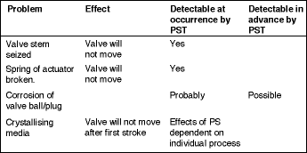
Issues still remain: What is the precise diagnostic coverage of this procedure? Due to the large variations in process conditions, there is certainly no general answer. A correct way of addressing this question could only start at the FMEDA of a shutdown system. For each failure mode it has to be asked whether it could be detected by PST technology or not. A failure table might look like this:

Only by making this specific breakdown, the benefits of PST could be made clear for a given process. Therefore, the conclusion is similar to the use of valves. The manufacturer can provide general data, the customer is responsible for analysing his process and making correct use of the data. A general statement like "...partial stroke can extend your process run time to..." makes no sense. Furthermore, a packaged bundle from one supplier consisting of positioner, actuator and valve should be more advantageous with regards to precise statements on diagnostic coverage than a combination of valve and positioner from different suppliers mounted first on site of the user.
How is a partial stroke approach validated?
Let us assume that, based on implementation of a PST, the inspection interval of a SIF is extended. But, the question remains, how can it be proved that a partial stroke has been performed? A detailed look into the documentation of the instrument of a leading manufacturer reveals that the approval for SIL use of a PST positioner is only valid for the ability to shut down the process. The diagnostic functions are not evaluated and consequently not approved. It is easy to understand this attitude, as it is very hard to approve the positioner software with all its functions. But, is it therefore possible to use the diagnostic information in a context for extending the safety review of a plant?
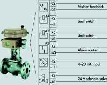
A different solution might be found in using a combination of a hard- and software package like the positioner outlined in Figure 1, as is provided by Samson AG. This package provides a positioner with PSD functionality as well as solenoid valve, P&F switches, and alarm output.

A configuration of this positioner wired to a HIMA safety PLC was tested. The positioner did perform the PST, triggered manually or automatically by timer. The event of the PST is recorded internally, diagnosis is performed. The diagnostic data allow the monitoring of graduation of valve performance over time. Key of the configuration is the recording of the PST by the HIMA safety PLC by means of P&F switches through the path:
* P&F switch.
* Input channel HIMA safety PLC.
* Logic on HIMA for event recording the PS is recorded with a precise time stamp in a chain of approved devices. There can be no doubt that the event has taken place.
This configuration makes another interesting monitoring capability possible. The diagnostic package of the positioner contains a datalogger. This datalogger is a monitoring function, recording valve movement and input signal over time. It can be triggered by the solenoid valve inside the positioner. Therefore, during shutdown or spurious trips, the complete closing run of the valve can be recorded.
This makes the proof and recording of valve testing very efficient, as any valve equipped with this feature can automatically generate a protocol on valve performance during shutdown testing.
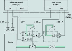
Not only closing of the valve can be approved; but there are also conclusions possible from parameters like dead time, closing time, closing speed and others which might lead to early recognition of valve failures. Spurious trips can be documented and used as 'valve tests' as well. These capabilities lead to a proposal for use of a positioner at an ESD valve (the example given in Figure 2 shows an instrumentation with safety valve and process valve as two separate units, other configurations with just one valve are equally well possible):

This configuration comprises the following instruments and features:
* The shutdown valve is equipped with an ESD positioner instead of a solenoid valve.
* The internal, certified solenoid valve is used for the shutdown function, triggered by the safety PLC.
* Partial stroke testing is possible through the positioner. It is commanded by the BPCS. All test data are stored in the BPCS and the general asset management environment.
* Partial stroke testing is signalled through the limit switches. The safety PLC performs the registration and time stamping.
* Valve diagnostic is performed inside the positioner at any valve movement (partial stroke test or full stroke test). Data indicating dead time, stroke speed, valve friction and others are stored internally and can be called up by the BPCS.
* An optional alarm output can signal any indication of valve degradation or a missing or faulty test. A compact solution as described in Figure 1 provides all functionality necessary in one device. The greatest benefit is not only in the cost saving, but there is also a significant gain in reliability due to the decreased numbers of interfaces.
All the mechanical, electro-pneumatic and electric interfaces between a combination of solenoid valve, limit switches, positioner are reduced to connecting just one housing to valve, actuator and system environment.
In conclusion:
* Precise assessment of reliability of final elements is still a challenge.
* Only very few valves come with reliability data supplied by the manufacturer.
* End-users have to assess their specific process conditions in order to generate reliability data for their safety loops.
* Testing procedures like partial stroke testing are coming up, but full benefit has to be exploited specifically for each plant and process.
* The future will most probably bring more detailed monitoring and recording of safety loops by end-users, supported by enhanced functionality of field instruments and especially positioners.
* Seamless integration of this enhanced functionality and the data recorded into the system environment and asset management procedures are mandatory as data, procedures, advances in technology are required from both sides, end users and manufacturers, success in these crucial points can only be achieved in the traditional way, close cooperation between suppliers and end-users.

© Technews Publishing (Pty) Ltd | All Rights Reserved