

Since the late '80s, standards for plant safety via 'measure, control, regulate' systems have existed in Germany. Risk evaluations are carried out according to DIN V 19250 and DIN V 19251 and the safety functions of plant components - eg, an overfill protection system - are categorised into protection classes running from 1 to 8.
The instruments are then selected according to the protection class required for the application. These standards are applied above all in the petrochemical industry, but also find use in the chemical industry. DIN V 19250 and 19251 are discontinued after next year, they will be replaced by IEC 61508 and 61511. These IEC standards have a wider range of application than the previous DIN standards - not only regionally, but also in industries where DIN standards were given little or no attention. Especially in the chemical and petrochemical industries, but also in all areas where dangerous materials are handled, these standards are gaining more and more relevance. In these areas of application, VEGA offers various sensor solutions for all hazard zones.
The earliest implementation of these new IEC standards began two years ago in Great Britain. Primarily in the petrochemical industry, the new standards were soon being considered in safety consultations. Meanwhile, the application of these standards has been extended to all areas of industry in Great Britain. The hazard potential of an industrial plant or a plant component is determined, as in the DIN system, by a risk diagram. In the so-called 'risk assessment', a safety-relevant part of the plant equipment is checked in detail. The criteria used are quite similar to those of DIN.
This test determines whether the component in question has a safety function and which hazard potential has to be protected against. The so-called Safety Integrity Level (SIL 1 to 4) that results describes the measures that need to be taken to manage the risk. To arrive at a SIL, the entire measurement chain has to be taken into account. The instrumentation of the application can then be carried out in two different ways.
1. Rely on tried-and-true instrument technology already used in the plant (service proven reliability).
2. Use instruments that are already SIL verified by the manufacturer.
SIL through service proven instrument technology
Plant components are considered service proven if a minimum number of them have been used over a defined period of time in the same or in a comparable application, and their function is determined to be 'reliable'. IEC 61511 stipulates a total application time of at least 30 million hours (including all instruments in use). Alongside IEC 61511, the NAMUR recommendation NE 93 also deals with the criteria for service proven reliability. This SIL rating is therefore based solely on the experience data of the user. If the reliability criteria are fulfilled and no malfunctions (or only acceptable passive malfunctions) occurred, the user can classify the instrument up to security level SIL 2.
The basis for this interpretation, ie, the SIL qualification, is a comprehensive statistical analysis of the failure mode of all sensors, logic units (such as a PLC) and actuators in question. PLCs actually have had such qualification for a number of years. The real problem here, however, is the application ie, the process itself. Where does one draw the line here, or in other words, using acceptable methods, how can one arrive at a reasonable conclusion?
In the chemical industry nearly all processes are different (product density, viscosity, pressure, temperature, mounting position, overflow/dry run protection, resistance, material, vessel size, etc). Qualification according to IEC 61511 (ie, service proven reliability) is practicable only with longer observation periods and, to be sure, only for larger companies. Moreover, the expense has to be weighed against the potential benefit. In the petrochemical industry the applied processes, from company to company and manufacturing plant to manufacturing plant, are generally quite similar. Qualification according to SIL within a particular industry is much, much simpler.
SIL qualification by the manufacturer
More and more manufacturers are starting to qualify their instruments according to the new standards (IEC 61508 and 61511) for functional safety. To design a measurement system correctly, the user needs from the manufacturer comprehensive data that provides the basis for calculating the parameters of such safety-related equipment. Some instruments, like the vibrating level switch Vegaswing 60, are already designed according to IEC 61508, which is rather uncommon at the present time. If an instrument is developed in conformity with the standards, it follows that all technical data and process parameters are already taken into account. The limitations of use are determined accordingly and noted in the safety manual along with the safety-relevant, basic technical data.
If a manufacturer goes beyond the scope of service proven reliability according to IEC 61511, as was the case for example with Vegapuls 40 and 50 radar sensors, he will have at his disposal far more data from past experience than individual users have. And that data will extend over the entire range of application of the instrument. In addition, the manufacturer must enlist IEC 61508 in order to carry out the FMEDA (Failure Mode, Effect and Diagnostics Analysis). This method of determining instrument reliability is still the norm at present. Indeed, Vega is taking this approach with instruments already on the market. Since of course the 30 million hour rule also applies here, a qualification on this basis could never be achieved for instruments newly introduced on the market. Only after the required test criteria have been fulfilled can the data pool be used to assess instrument reliability.
Design of a SIL measurement system
When previously, according to DIN V 19250 and 19251, every participant of a measurement chain, ie, safety loop, was in class AK 4 (then the entire measurement chain was in class AK 4). The situation is somewhat different with IEC. If an instrument has no SIL classification, it can be used on the basis of the safety characteristic values in a measurement chain according to a SIL X. These safety characteristic values can be found in the technical documentation or in the safety manual of the instrument. Among other things, the probability of dangerous failure (PFD) is one of the most important parameters. It represents the primary factor in determining whether and in which SIL the instrument can be classified.
SIL 2 requires, for example, that the dangerous failure probability of a measurement chain be between 1 x 10⁻³ and 1 x 10⁻². In contrast to the DIN system, the PFDs of the measurement chain participants are added together. It must be assured therefore, that the sum of the PFDs of all participants, for example with SIL 2, does not exceed the value of 0,99 x 10⁻².
Thus it can easily happen that a measurement chain consisting of components presumably suitable for SIL 2 suddenly has an effective total that results only in SIL 1. To nevertheless be able to use these components, several things can be done: pair the instrument, connect it in an 'OR' circuit (1oo2), or shorten the prescribed test interval. The PFD of the measurement chain is hereby reduced and the required SIL again reached.
Recurring function test of a SIL measurement system
SIL also implies a recurring function test whose test cycle is determined by the measurement chain as a whole. The probability of dangerous failure (PFD) is thus an important parameter not only for the layout but also for the test interval. Since the PFD generally applies to use over a period of one year, the test interval is also one year. As with WHG (Water Resource Law) overfill protection, a wet test (raising level to contact point or dismounting) for example, must then be carried out (unless otherwise specified). There are several variations with the Vegaswing 60 vibrating level switch:
1. If the Vegator 636 conditioning instrument is connected, a simple press of the test key suffices. After the key is pressed, the sensor runs through a function test encompassing all possible fault conditions and the conditioning instrument switches the relay output accordingly. All other connected devices - ie, the whole measurement chain - are thus also tested. The test interval in this case is one or two years.
2. If the Vegaswing with 8 mA/16 mA electronics is operated directly via a PLC, the PFD of the measurement chain decreases considerably and has an affect on the length of the test interval. With such a measurement system design, the test interval can actually be five or more years. The function test is carried out by briefly disconnecting cable from the sensor and injecting a signal that reflects the desired switching conditions.
3. If the instrument is equipped with NAMUR electronics, the test interval is a similarly long period. A wet test is however still required.
Depending on the respective PFD and the SIL that has to be reached, the test interval can be shorter or longer than a year. It is assumed that the PFD of an instrument at the time of set-up as well as after conclusion of a test is zero, and that after one year the stated value is reached. A linear characteristic curve (Figure 1) is also assumed. For example, if the test interval is reduced to a half year, the PFD of the measurement chain is also halved accordingly. If the test interval is increased to two years, the PFD is theoretically doubled. A short example demonstrates this:
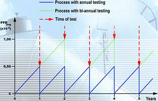
SIL 2 (1,0 x 10⁻²) is required
The PFD of the entire measurement chain is 0,49 x 10⁻² (SIL 2).
The result for a test interval of two years is 0,98 x 10⁻² (2 x 0,49 x 10-2) = SIL 2.
In spite of the lengthening of the test interval, the required SIL 2 is maintained.
Vega instruments fulfil the requirements of SIL 2 and SIL 3
Due to its high reliability, the Vegaswing Series 60 vibrating level switch can be used with different electronics versions in measurement systems where SIL 2 and SIL 3 are required. It can be used on one channel in SIL 2 and redundantly with a 'one out of two' (1oo2) evaluation in SIL 3.
The application criteria of the NAMUR recommendation NE 79 up to hazard zone II are thus fulfilled. The Vegapuls Series 40 and 50 radar sensors in 4 to 20 mA output (loop powered) version meet the requirements for use in SIL 2 applications. They can be used for overfill and dry run protection or integrated in safety-relevant measurement systems according to SIL 2 for operation in continuous mode.
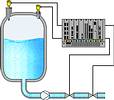
In hazard zone II (SIL 3), Vegapuls radar sensors can, for example, be combined with a Vegaswing 60 ('OR' circuit). The advantage: continuous measurement is included in the safety concept (Figure 2); in addition, the overfill protection is diversified.
For the user, the issue of cost of such systems is of course very important. Beside the expense of determining risk coverage and measurement chain layout, no further costs arise when Vega instruments are used. The SIL-relevant data as well as all other technical data can always be found in the operating instructions of the respective instrument. So with Vega, SIL does not mean additional instrument costs.
1oo1 or 1oo2 for hazard zone II?
Another question arises - particularly in connection with hazard zone II (SIL 3): How high is process availability when, instead of two independent instruments in 1oo2, only one single (1oo1 - one out of one) SIL 3-rated instrument is used?
Once the process equipment is brought into a safe condition through such a system, it must be kept there (acc to norm) until the system is again fully functional. In a 1oo2 evaluation, however, the process equipment can under certain conditions continue to operate in spite of a defect in a 'measurement chain participant', which would certainly keep process availability at a high level even in case of component breakdown. NE 93 also follows the philosophy of 1oo2 in this particular hazard zone.
Outlook
Due to the universal specifications in the extremely comprehensive IEC standards, the area of application will spread, as it already has in Great Britain, to all industries. For the individual user, however, considerable expense is involved in plumbing all aspects of functional safety and carrying out a risk assessment. Various software tools have already been developed which the user can apply in the safety consideration and which consequently simplify instrument selection and system layout. Yet it remains the responsibility of the plant operator to decide which safety technology his plant will be equipped with. To always use instruments with the highest safety level (SIL) is, to be sure, a pragmatic solution, but again would lead to considerably higher procurement costs. With SIL 3 and higher, for example, we are talking about redundancies that will noticeably affect the cost of a measurement system. Dealing with the new standards and applying them sensibly certainly involves a lot of time and effort. But in the end, it is and will likely remain the best way to arrive at an economically reasonable solution.
| Tel: | +27 11 795 3249 |
| Email: | [email protected] |
| www: | www.vega.com/en/home_za |
| Articles: | More information and articles about VEGA Controls SA |


© Technews Publishing (Pty) Ltd | All Rights Reserved
 printer friendly version