


The combination of Control Techniques' drive and fieldbus technology and Qualter Hall's mechanical design is giving history a `lift' at the recently opened Standedge Visitor Centre at Marsden, as part of a £30m restoration project on the Huddersfield-Manchester canal. A CTNet-linked, 4-axis Unidrive system is providing accurate control of a Qualter Hall-designed lift system for hoisting 16 tonne canal boats out of the water at the prestigious new centre. This enables passengers - including the disabled, to embark and disembark easily and safely.
The new visitor centre is adjacent to and serves the Standedge Tunnel; the highest (196 m), longest (5200 m) and deepest (194 m) canal tunnel in the UK. Running beneath the Pennines, the tunnel was originally built to serve England's booming textile industry in the 19th century. Over the last few decades it had fallen into disuse, as had a large section of the Huddersfield-Manchester canal of which it is part. Recently, British Waterways decided to do something about this situation and embarked on a £30m project, part funded by the Millennium Commission and English Partnerships, to restore the 190-year-old tunnel and 20 miles of canal. Now complete and recently opened by Prince Charles, the project overall is a showcase of restoration, epitomised by the new visitor centre, which brings all aspects of the tunnel and canal history to life for the public at large.
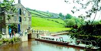
Located in what used to be the canal winding house, the visitor centre is unique as the canal actually enters its confines via a spur from the main channel. The spur allows 15 m barges to be accommodated for the easy boarding of up to 30 passengers, who then travel though the tunnel. Central to the boarding operation is a 4-axis lifting system that actually hoists the 16 tonne canal barge 1,6 m out of the water, at a rate of 1 m/min, to the level of the visitor centre floor.
The lifting system was designed, manufactured, installed and commissioned by Barnsley-based engineers, Qualter Hall. Fittingly, Qualter Hall began their engineering operations 140 years ago when the Standedge Tunnel was probably at the height of its use.
The company was, for many years, a mainstay of the mining industry, providing engineering solutions for the raising and lowering of all types of heavy loads in mine shafts. Today, Qualter Hall is far more diversified, but its design solution for the boatlift system still owes much to its previous experience in the mining industry.
At the heart of the lift system is a cradle upon which the boat rests. The cradle is a ladder type structure linking between the two main crossbeams of the lifting device. It is equipped with a number of rubber support pads to protect the bottom of the boat and allow its mass to be distributed more evenly.
Once manoeuvred into position upon the cradle, the boat is elevated from a lowered position to a raised position, precisely, by four screw twin actuator systems. These are driven by individual motors and are electronically synchronised by a fieldbus-linked (CTNet) Unidrive inverter system, operating in flux vector mode to ensure the optimum torque for lifting.
The 4-axis Unidrive system, including both hardware and software, was designed and built by Control Techniques' systems engineering division. It consists of a master Unidrive and three slave Unidrives, each controlling individual screw jack motors (master drive 1, slave drive 2, slave drive 3 and slave drive 4). The inverters operate in closed loop flux vector control with position and speed calculated from an encoder mounted on each motor shaft. The master Unidrive contains the sequence control software running in a second onboard processor, Control Techniques' UD75 unit. For normal operation the drives all need to be on-line and the datum set. Position is then calculated from the datum limit (the datum limit represents 0 position).
Each screw jack has three normally closed limit switches, ultimate top and bottom limits and a datum limit set near to the bottom limit. In addition, there are two preset software limits, a top stop limit and a bottom stop limit. When the drive system receives a raise command, the Unidrives are enabled, with the master drive speed reference set to zero. The brakes are then lifted and the zero speed reference clamp released after a set time delay. The top stop limit is then compared with the position feedback signal. If the position error is greater than the first preset stop distance then the master drive receives a maximum speed reference.
If the error is between the first and second preset stop distance then the master Unidrive receives the first slowdown speed reference. When the error is below the second preset stop distance the master drive receives a creep speed reference. If this is equal to, or less than 0, a zero speed reference is set. Upon zero speed being detected, the brakes are applied and the inverters are disabled. The same process also occurs in the opposite direction.
The master encoder for the system is connected to a second encoder card on Unidrive 2, as well as being connected to the master Unidrive unit. Slave drive 2 then re-transmits the encoder pulses to the encoder cards on slave drive 3 and 4. This design reduces the electrical loading on the master encoder. The slave drives use the master encoder pulses to operate in rigid digital lock mode therefore copying the master drive position.
The drives are also linked together via CT-Net communications. The master Unidrive globally transmits common data to all the slave drives, including a run command, and each slave transmits its own reply. The position of each slave drive is sent back to the master, enabling the drive speed reference of this unit to be reduced if a slave drive is not maintaining the correct position. This function prevents the system running if one jack becomes mechanically jammed. In addition, if any of the jacks trigger the mechanical top or bottom ultimate limits, then all the Unidrives will be disabled in the relevant direction.
As an alternative to automatic operation, each Unidrive is equipped with inch raise and inch lower pushbuttons. These are enabled if local control is selected. The master Unidrive inch pushbuttons operate the complete drive system at an inch speed in digital lock. However, the slave inch pushbuttons provide a relative inch of a slave drive with respect to the master drive, without digital lock. This can be used to level the lifting cradle before moving it to the datum position.
Overall, the performance of the Control Techniques' drive system is described by Paul Jones, engineer in charge of the project for Qualter Hall, as 'amazingly accurate'. "We are well used to the precision of Control Techniques' drives on mine winders, so they were the first choice for this project," he said. "We also have a first class relationship with Control Techniques' systems engineers, which is crucial to getting things right first time."
| Tel: | +27 11 462 1740 |
| Email: | [email protected] |
| www: | www.controltechniques.com |
| Articles: | More information and articles about Nidec Control Techniques |


© Technews Publishing (Pty) Ltd | All Rights Reserved
 printer friendly version