



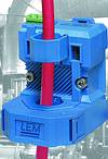
Electricity is the 'lifeblood' of industry and, thus, is an ideal starting point for the control, monitoring and protection of manufacturing process systems. LEM, a specialist in the measurement of electrical parameters, has introduced a generation of current transducers based on a new technology.
Manufacturing processes require continuous collection and analysis of operating data in order to provide realtime event, batch and historical information that can be transferred directly to the business system. Traditionally, magnetic current transformers (CTs) are used for measuring AC currents. LEM has developed a new product family based on a technology it calls 'PRiME' (Planar Rogowski I MEasurement) which looks set to open up new opportunities and applications for current measurement.
Usually, automated processes are regulated by parameters such as temperature, pressure, torque, position, etc. However, measuring the input current of the load provides more information than the current value alone and has the following advantages:
* Faster, because load changes are immediately detected and can prevent equipment failure and process disruption.
* Easier, because the transducer can be simply snapped over the cable without the need to screw or weld on complex brackets.
* More reliable, because solid-state transducers are more robust than electromechanical devices.
* Economical, because cost is reduced through quick and easy installation and long-term reliability.
Technology overview
New measurement trends demand higher performance characteristics such as accuracy, bandwidth or split-core functions to reduce installation time which existing CTs cannot fulfil at the required cost. The new technology features a means to solve the inherent limitations of existing CTs caused by their magnetic circuit. The new system still operates on the same basic Rogowski method as first outlined in 1912, where a coil is magnetically coupled with the flux created by the current to be measured.
A voltage signal is induced into the coil proportional to the flux derivative and thus proportional to the derivative of the current to be measured. Originally, the Rogowski principle was based on a single wound coil. Manufacturing tolerance of these coils, together with the effects of differences in the position of the primary cable in the aperture and also influences from stray external fields created, for example, by the proximity of another cable, would all effect the accuracy of the measurement.
The new technology works to avoid these problems by using two parts for the transducer head (Figure 1), a number of sensor printed circuit boards (PCBs), and a base-PCB.
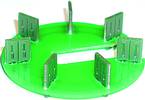
The sensor PCB consists of two separate air-cored coils constructed on a multilayer PCB (Figure 2).
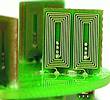
Several sensors are mounted onto the base-PCB, at right angles to it, and connected in series to form two concentric inner and outer loops (Figure 3).
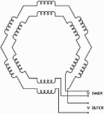
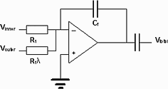
To facilitate measurements, the current carrying conductor needs to be positioned within the aperture of the transducer head (Figure 1). This creates an AC magnetic flux, which is coupled into the sensors and induces a voltage proportional to the rate of change of the current (di/dt) (Figure 3 -Vinner and Vouter).
The signal Vtotal (Figure 4), used for the current measurement is:

Vtotal = total voltage
Vinner = voltage switched in series to the internal coil
Vouter = voltage switched in series to the outer coil
As mentioned previously, the sensitivity to the external sources of perturbations is traditionally the main disadvantage of the wound coil Rogowski principle. However, 'PRiME' has been designed using a new type of compensation technology, which means there is little effect from external sources. Indeed, for an external parasitic current source, the essence of the technology is that the ratio of the induced voltage in each loop of sensor PCBs (Vouter/Vinner) is almost constant, irrespective of the magnitude or position of this external source. As a result, the external field effects are cancelled if the correct proportion of the induced voltage in the outer loop (Vouter) is subtracted from that in the inner loop, Vinner eg, by choosing γ = Vouter/Vinner implies Vtotal = 0.
To measure the current from the conductor placed within the aperture, an optimised transducer design leads to a typical Vouter:Vinner ratio of γ/2, again irrespective of the position of the primary cable. As a result, the usable signal for the measurement is close to Vtotal = Vinner/2, meaning that approximately half of the signal collected by one concentric chain of sensing PCBs is used for the measurement.
Finally, since the collected signal is proportional to the current derivative, it is necessary to integrate the induced voltage in the transducer head to obtain both amplitude and phase information for the current being measured. The integrated circuit (Figure 4) is kept as close to the transducer head as possible in order to reduce stray inductive pickup that could cause errors.
PRiME uses an air-cored coil as the sensing element, which means there is no magnetic hysteresis, saturation, or non-linearity, as there is with existing CTs, which have a magnetic core. The advantages of the current transducers based on PRiME:
* Wide dynamic range (typically 1000:1 ratio for a given transducer) capable of withstanding high overload.
* Large bandwidth (several kHz).
* Products are lightweight in comparison with their standard CT counterparts.
* Better accuracy over measuring and temperature range.
* Easier to design a clamp-on device (no complex mechanical case requiring a minimum air gap).
* Provides low voltage, isolated output signal (eg, 4-20 mA) which does not require additional safety precautions.
A new generation of current transducers has been designed to meet the demands of the new trends in current measurement: higher sensing performance and quick installations. These transducers also incorporate the calculation of the RMS current. In the AP series the calculation of the RMS value is based on the 'average' principle, which is a simple calculation of the rectified signal multiplied by a gain. This series is, therefore, suitable for pure sinusoidal current when the load is linear and there is no noise on the measured signal. In the APR series the RMS calculation is based on a mathematical algorithm called 'True RMS,' which integrates the actual waveform over time. Therefore, this series is suitable for complex waveform when the load is non-linear or in a noisy environment (eg, close to a rectifier or drive).
To reduce installation time, the DIN standard has been selected both for its simplicity and reliability.
In addition, the advantage of the split-core function is that it enables high flexibility for retrofit applications and also for new cabinet cabling. Indeed, by avoiding cable disconnection when having to pass it through the transducer aperture, the operator can position and connect all cables and install the transducer at the end, reducing installation time.
The technology offers a substantial reduction in weight, which is a key benefit of the AP and APR range, especially, in applications where cables are squeezed into a limited space and access to the cabinet panel is restricted. Instead, the transducer can be fixed easily and directly around the cable or it can be allowed to float. Weight reduction also has a big impact on shipment cost, with the manufacturer claiming as much as 50% differences for higher rating above 100 A.
Current transducers available on the market usually have their aperture parallel to the DIN profile. Therefore, when the cable passes through the hole, there is a significant loss of space on both sides, especially for three-phase systems. Because the AP and APR have been designed with a hole perpendicular to the DIN profile, this problem is solved and transducers for a three-phase system can be installed with minimum space loss.
AP and APR are available in 12 different ratings from 10 A to 400 A. To reduce the number of references and simplify stock, each model offers three selectable ratings. For output and power supply there are two options available- either 4-20 mA loop powered or voltage outputs of either 0-5 or 0-10 V with an external +24 V d.c. power supply.
The unique PRiME technology provides transducer immunity against saturation due to over-current conditions while maintaining absolute accuracy of more than 1% over a broad range of inputs. The coreless design permits a wide bandwidth from 10 Hz to 1 kHz, which is particularly useful for applications using inverters or ballast where frequency and noise can be important.
The AP and APR series conform to EN 50178 and EN 61010. All these transducers offer a 5,5 mm creepage and clearance distance and withstand 5 kV for one minute during an AC isolation test at 50/60 Hz. All materials are UL94V0 and the transducers are CE marked in accordance with European EMC Directive 89/336/EEC and thus comply with local EMC regulations.
LEM's AP/APR series current transformers are available locally from Denver Technical Products.
For more information contact Denver Technical Products, 011 626 2023, www.denvertech.co.za






© Technews Publishing (Pty) Ltd | All Rights Reserved
 printer friendly version