

In the last of a four-part article, we look at the correct ranging of transmitters and methods of suppressing redundant alarms.
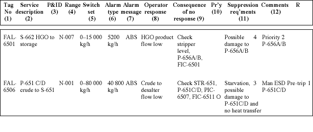
The importance of correctly ranged transmitters to cover all of the alarm settings is often overlooked, specifically on level applications. If we take for example a level installation, the transmitter must cover the range of any level switches or an additional transmitter used for trip purposes. Typically one would set the low and high level 'control' transmitter pre-trip alarms at say 25 and 75%, with the trip switches at 5 and 95% of the control transmitter range. How often have you seen level switches installed outside of the indicating or control transmitter range? There should always be sufficient time between a pre-trip alarm and a trip alarm setting for the control system or operator to attempt corrective action, if there is not, then there is little point in having a pre-trip alarm. Trip or safety related alarms should always be implemented in a separate measurement loop and system to the normal process control system. This also applies to field instrument process connections in order to eliminate a source of common mode failure. This is a requirement of IEC 61508, for applications above SIL 1. It is good design practice to display the actual trip value on the same control system (DCS) instrument tag faceplate, as the pre-trip alarm setting. This will then always be visible to the operator as the process variable approaches the actual trip point, how much beyond can also be important for equipment stress, not to mention human stress at the time. This actual trip setting is required should the trip protection instrument be on override for test or maintenance, as the operator must know when to safely actuate the Manual Trip, but how often is this trip setting displayed to the operator? It is important to document all alarm settings and relevant information on an alarm/trip schedule, refer to Figure 1 for a typical example. This schedule includes information not normally presented, such as 'operator response' as well as 'consequence of no response' and 'suppression requirements'. This is critical information in assessing the need for alarms and allocating their respective priority. This important schedule must be available for the unit HAZOP and form part of the plant-operating manual; needless to say, it should be kept up-to-date, which raises the thorny issue of 'change management'.
Alarm suppression
There are four basic methods for automatically suppressing alarms, which will probably cover 95% of all 'nuisance' type alarms following plant upsets:
* Event based.
* Time based.
* Priority based.
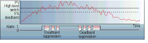
* Applied deadband.
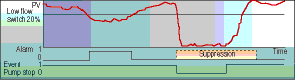
Event based uses a related event to suppress an alarm; it could be the status of operating equipment or in some cases an analog process value. A typical example is that of a low flow alarm which would be suppressed if an associated pump were stopped. When the pump is restarted, a timer holds the alarm off for a short period, until the flow would be expected to have transgressed the low flow switch setting. This type of suppression is common for automatically overriding trip alarms in order to reset and restart a tripped ESD group; it prevents the problems inherent with 'manually' operated start-up overrides. This action is shown graphically in Figure 2a.
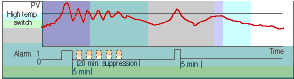
Time based uses a set time to suppress a repetitive alarm, sometimes referred to as 'auto-shelving'. If an alarm attempts to repeat itself within a set period, say 5 minutes; it is suppressed for a further 20 minutes or whatever period is suitable to cover the specific process dynamics. An optional variation is to reduce the suppression time, but to automatically reset the suppression period, should any subsequent alarm attempt occur within the suppressed period. This is a useful alarm filter used where the process cycle following a large upset, has a medium to long time constant. This action is shown in Figure 2b, where the initial alarm is processed but the following five in the specific time period are suppressed.
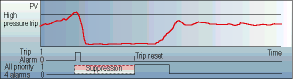
Priority based suppresses all new low priority four alarms should a priority one or two alarm occur. This eliminates all subsequent low priority alarms during this critical operating period, which are mostly responsible for the undesirable alarm flooding phenomena. If a manual unit trip is operated, then all associated priority two pre-trip alarms ie priority three alarms, are also suppressed, as there is no need following a 'manual' trip to have both alarms. These low priority alarms remain suppressed until a trip reset (not restart) is initiated or the higher priority alarms return to normal. The trip reset action may well release a number of previously suppressed alarms, but they are not at a critical phase of plant operation and can be calmly accepted. This action is shown in Figure 2c.
Applied deadband is a form of suppression, which requires the process alarm to fall below a set differential or deadband before the alarm is automatically reset. A typical application is on a short time constant or 'noisy' signal such as with some level measurements. The deadband is normally set at about 5% eg if the high level alarm is set at say 75%, it will have to fall below 70% before it is reset and the alarm extinguished. This action is shown in Figure 2d, the initial alarm is processed and the following six alarms are suppressed.
Internal damping can also be applied electronically within current transmitters. This is easily implemented if the signal is analog, digital inputs from level switches are not quite as easy. There is however, some inherent mechanical deadband (sometimes adjustable) with process switches, also, if the signal has a short cycle frequency (less than 10 s) a 5 s timer can be used to delay the alarm from resetting.
This article has highlighted a number of topics on the causes and subsequent management of abnormal process situations. The enormous benefits in the use of these AMS applications can be realised on most existing plants, within their current control systems, provided that they are DCS/PLC based. They complement recognised advanced process control (APC) strategies, as tools to minimise lost opportunities by maximising equipment and process safe operating duration and hence company profitability. Greater production and operating efficiency with increased safety protection, should be an objective of any company business plan, can we compete against world-class organisations and 'not' afford to implement such ASM practices?


© Technews Publishing (Pty) Ltd | All Rights Reserved
 printer friendly version