

Perhaps your line of work has never required you to understand the inner workings of some of the instruments of your plant. But have you ever wondered how some of the different flow measuring devices work? This article gives a brief description of five different flow measurement methods.
Variable area flowmeters
Variable area flowmeters feature an upright tapered tube, wider end up, in which a specially shaped float moves freely up and down. The fluid flows upwards through the tube, causing the float to lift a certain distance and form a gap between tube wall and float, so that the forces acting on the float are in equilibrium. The float position corresponds to a particular flow rate that can be read from a scale.
Three forces act on the float:
* Gravitational force - which is constant.
* Buoyancy which, according to Archimedes' principle, is constant if fluid density is constant.
* The upward force of the fluid flowing past the float, which depends on the flow rate.
The metering tube is usually conical in shape. With glass cones, the flow value can be read directly from a scale at the level of the float reading line. With non-transparent cones, eg made of metal, the float position is transmitted to an indicating instrument by magnetic or inductive means.
The described measuring principle can also be used on instruments with reversed geometry, ie where a conical float moves in a cylindrical tube fitted with an orifice to form the variable flow profile.
Recognised methods are used to calculate scales for variable area flowmeters to include all flow parameters, eg density, viscosity, pressure, and temperature of the fluid. These methods can also be used for scale conversions to accommodate changed metering conditions.
Vortex flowmeter
The vortex flowmeter is used for measuring the flow velocity of gases and fluids in full filled pipelines. The measuring principle is based on the development of a Karman vortex-shedding street in the wake of a body built into the pipeline.
The periodic shedding of eddies occurs first from one side and then from the other side of a bluff body (vortex-shedding body) installed perpendicular to the pipe axis. Vortex-shedding generates a 'Karman vortex street' (Figure 1) with alternating pressure conditions whose frequency is proportional to the flow velocity. These vibrations are detected and a flow measurement is derived from the frequency
Electromagnetic flowmeters
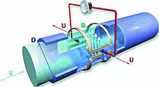
Electromagnetic flowmeters measure the volume flow of electrically conductive liquids and slurries. In Figure 2, an electrical conductor, in this case the electrically conductive medium being measured, passes through a magnetic field. The voltage (U) induced in this medium is directly proportional to the mean flow velocity (v). Magnetic field strength (B) and the distance between electrodes (D) are constant. The induced voltage signal is picked up either directly, by two measuring electrodes in conductive contact with the medium, or indirectly, by capacitive coupling.
A signal converter amplifies the signal and converts it into a standard analog signal (eg, 4 to 20 mA) and a frequency signal - eg, one pulse for every litre or cubic metre of medium flowing through the measuring tube.
To ensure that the voltage is not short-circuited by the pipe wall, the measuring tube is made of an electrically insulating material or fitted with an insulating liner. Measurement is largely independent of the flow profile and other properties of the medium, such as pressure, temperature, viscosity, density, consistency, electrical conductivity and electrode contamination.
In typical measuring systems, the electromagnetic flowmeter consists of a primary head, which is installed in the pipeline, and a signal converter. This compact design has the signal converter mounted directly on the primary head. For systems with pulsed DC field the primary head field coils that generate the magnetic field are energized by a pulsed direct current from the signal converter. The measuring signal is a squarewave voltage of the same frequency. This method of measuring flow typically exhibits great accuracy.
Ultrasonic flow meters
The basic idea of the transit time differential method is quite simple and can be illustrated with the following example. Imagine two canoes crossing the river over the same diagonal line in two opposite directions, one going downstream (with the flow) and one going upstream (against the flow). The canoe going with the flow will take less time to reach the other side of the river than the one moving against the flow.
Ultrasonic flow meters use acoustic waves or pulses that are sent through the medium in order to establish the volumetric flow rate. Sound waves or acoustic signals behave in the same manner as the canoes in the example.
One transducer transmits a signal in the direction of fluid flow. A second transducer transmits a signal upstream, against the flow, and along the same path. A sound wave going with the flow travels faster than one propagated against the flow. The time the acoustic pulses take to travel across (with and against the flow) is measured very accurately. The difference in transit times is directly proportional to the medium's mean flow velocity. The volumetric flow rate is the product of the mean velocity multiplied with the cross-sectional area enclosed by the pipe.
Coriolis mass flow measurement
Coriolis forces are generated in oscillating systems when a liquid or a gas moves away from or towards an axis of oscillation. A Coriolis measuring system is of symmetrical design and consists of one or two measuring tubes, either straight or curved. A transducer built into the instrument sets the measuring tube into a uniform fundamental oscillation mode. When the flow velocity is zero, the fluid in both ends of the measuring tube experiences equal acceleration and deceleration (from the oscillating tube) and sensors on the ends of the tube detect no difference.
During flow conditions, when the pipe vibration causes the fluid to be accelerated in one half of the pipe, while at the same moment the fluid in the other half of the pipe is decelerated. This causes a minute distortion of the shape of the measuring tube. Sensors detect the distortion caused by the resultant (Coriolis) forces, and the mass flow rate is derived from the outputs of these sensors. Since the oscillatory characteristics of the measuring tube are dependent on temperature, the temperature is measured continuously and the measured values corrected accordingly.
Krohne produces quality flowmeters suitable for many applications.
For more information contact Gordon Duff, Krohne, 011 315 2685, [email protected], www.krohne.com
| Tel: | +27 11 314 1391 |
| Email: | [email protected] |
| www: | www.za.krohne.com |
| Articles: | More information and articles about KROHNE |


© Technews Publishing (Pty) Ltd | All Rights Reserved
 printer friendly version