

It often happens that experience gained in one industry can be carried across and used to great advantage in others. Perhaps your organisation has a difficult level-sensing problem that could benefit from this approach. Here we see how a way was found to establish the levels of various substances in a tank, when there are four or more – and partial mixing of these substances blurs their interfaces. Raymond Lees discusses the difficulties had in separating oil and gas from water and mud in an undersea Kuito oilfield.
The Kuito field, discovered in April 1997, lies offshore Cabinda Province in Angola's deep-water Block 14, a 1,560-square-mile concession. Kuito was Angola's first deep-water oilfield to come on stream in December 1999, two and a half years after discovery. Kuito oil is produced via an FPSO chartered through SBM of Monaco and Sonangol on behalf of operator Chevron Texaco.
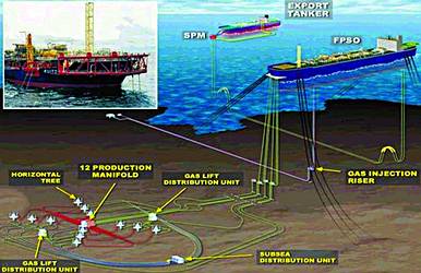
Kuito is a heavy oil ranging from 18-22 API. The FPSO presently has two oil production trains with a maximum throughput of 100 000 bbls oil per day. Three phase, horizontal, gravity separation vessels are used to separate oil and gas from unwanted produced water and solids prior to transportation. Kuito production separators were designed with traditional, single point transmitters for interface and bulk level measurement. These level transmitters were capacitance type instruments mounted inside the vessels in stilling wells.
Following production start-up, separation problems began to emerge, these were manifested in numerous process upsets and shutdowns. Kuito oil can form emulsions quickly and calcium naphthenate, or 'Kuito Gunk' as it is referred to on the FPSO, is produced at higher temperatures and if allowed to cool solidifies. The point instrumentation was unable to detect these emulsion and naphthenate layers resulting in the instrumentation becoming fouled and ceasing to function. The separators were operated 'blind', utilising tri-cocks located on the side of the vessel and as the instrumentation was installed in stilling wells inside the vessel it was impossible to maintain them without shutting down and depressurising the vessels. This article describes how nucleonic profiling instruments were retrofitted to the vessels and shows, with the aid of realtime on line screen shots how operations were able to identify the different layers within the separators. This enabled oil production uptime to be increased and chemicals, emulsion breakers and defoamers, to be pro-actively dosed before the plant became unstable.
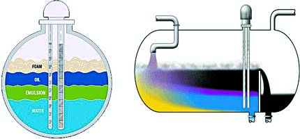
Well fluids are routed to two parallel production separators. These vessels are long horizontal cylinders, 3,6 m in diameter and 12 m in length with a weir positioned at one end, 7 m from the inlet. Well fluids enter the separator as a mixture of oil, water, gas and sand. As the fluids flow along the vessel they start to separate, under gravity, into their constituent parts. In order to have within-specification oil flowing over the weir and uncontaminated water at the water outlet, it is necessary to control the flow-rate. The only way to control this effectively is to accurately measure the levels of the various phases at the weir. Often there was not a distinct interface in the separators, but rather a continuous graduation from one phase to another, eg from water to emulsion to oil, or from oil to foam to gas. In these cases, phase identification by simple interface detection is difficult at best, and impossible with conventional type instruments. To aid separation, expensive chemicals, emulsion breakers and defoamers are injected into the well streams.
The production separator level measurement was designed with conventional separate, single point instrument transmitters for oil/water interface and bulk oil level. Capacitance type probes were installed inside stilling wells to measure the level and interface. Two stilling wells, each 6" diameter, were located approximately 1 m upstream of the weir for interface control and trip functions. Two stilling wells, again 6" diameter were installed 2 m downstream of the weir for bulk level control and trip functions. A level sight glass was installed upstream and downstream of the weir. At 2 m upstream of the weir, 5 tri-cock valves were located vertically to cover the interface range. Kuito separators operate with a 'flooded' weir.
Capacitance probes
The original capacitance probes, operated by measuring electrical characteristics which were dependent on the levels of fluids in contact with the probe. As an interface level rises on the probe, the measured capacitance changes as the probe goes from complete immersion in oil (0% on the interface level range), to complete immersion in water (100% on the interface level range). The problem with this method is that the electrical characteristics of either fluid can change significantly from the expected values, as happens when different wells are introduced to the vessel or when emulsions are formed, then the capacitance measured will change. This will be interpreted incorrectly as a change in level resulting in misinformation being presented to the operators and inappropriate control actions. These instruments are only suitable where a well defined step change in densities is evident ie a step change from 100% oil to 100% water, in practice this was rarely the case on Kuito.
Operational problems
The most significant problem with the capacitance instruments was that the stilling wells blocked up with naphthenate and the probes were coated in this substance rendering them ineffective. The operators had to constantly manually check where the interface was based on samples taken at the tri-cocks on the side of the vessels. Incorrect or lack of separation information caused numerous process upsets and shutdowns due to high concentrations of oil carried through the water outlet, overloading downstream de-oiling equipment. It caused high concentrations of water to be carried over with the oil phase and hence cause downstream knock-on separation problems. Solids accumulation reduced the working volume of the vessel and therefore its efficiency. All of these problems resulted in unnecessary trips and production problems. As a result, output, quantity and quality, suffered; spend was high on effect chemicals; maintenance and operator input was intensive.
Profiler installation
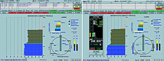
In Jan 2000, Chevron commissioned their first Tracerco Profiler on the Alba Northern Platform in the UK sector. Alba oil has a similar API as that of Kuito, 19 deg. Alba at that time had similar separation problems and the installation of the Profiler proved very successful in identifying emulsion and suspended solids within their separators. This success was reported within Chevron and brought to the attention of Block 14 Operations. Early in 2001, after Kuito's first year of difficult production, discussions were started to replace the existing level instruments with Tracerco Profilers. Orders were placed in mid 2001 and in August/September 2001 during a planned shutdown the stilling wells and interface capacitance instruments in the two production separators and the test separator were replaced with Tracerco Profilers. The three profilers were commissioned in September 2001. The profiling instruments defined all the fluids inside the vessel to a far greater degree than the conventional instruments. In place of the traditional two single points, oil / water interface and bulk oil level, the operators could now see all the phases and the quality of the interfaces.
A density profiler was housed in dip-pipes (sealed pockets similar to thermo-wells) that were installed within the separator through the single 6" flange that previously housed the stilling well instrument.
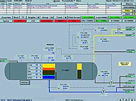
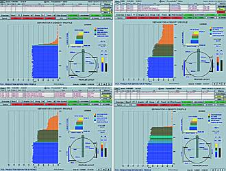
The screen shots show what the operator could see realtime on Kuito, during start-up and production.
The technology
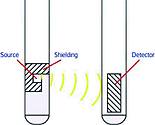
A narrow dip-pipe holds an array of Americium-241 sources, a low energy gamma emitter. The other dip-pipes hold radiation detectors made up of a vertical array of 80 Geiger Muller tubes (44 tubes for the smaller test separator), each one 28 mm in height. Each tube is matched to the radiation source on the same plane. The material between the two dip pipes will attenuate the radiation; the intensity of radiation seen by a GM tube is related to the density of the intervening material. The counts from the GM tubes are transmitted for analysis via fibre optic links and RS232 converters to the existing Moore Quadlog DCS that collects the information and calculates the density of the material for each individual GM tube. Thus, a density profile of the vessel can be achieved. Density bands are allocated for each of the different phases; the top level of these phases can then be calculated with respect to vessel or instrument height. These heights and phase band thickness are then used for control loop process variables.
Titanium was chosen for the dip pipes because it is transparent to the low energy 60KeV radiation emitted from the Americium sources. Americium-241 is the same sealed radioactive source as used in domestic smoke detectors. It is the use of low density, high strength titanium for the dip pipes that make it possible to use low energy Americium-241 sources in the profiler. Americium is much easier to shield and allows a smaller source to detector distance, this allows a single nozzle on the vessel and allows much improved vertical resolution, hence better density profile.
Feedback
After six months of production, post profiler installation feedback from the operators SBM and Chevron Texaco is that "the Tracerco Profilers have proved not only to be totally reliable and basically trouble free but also a very important tool for managing the levels within the process".
Within the process system on Kuito, water knock-out is an important aspect. Water knock-out can only be achieved effectively with the correct dosage of emulsion breaker chemicals into each train. Because the Tracerco Profilers clearly identify the emulsion phase within the vessels, we are quickly alerted to any adverse shift in chemical dosage rates and are then able to do something about it in a proactive manner. Prior to the installation of the profilers, we would often find ourselves in an unstable or trip condition before we realised there was a problem with the chemicals. The same applies for the defoamer chemical. It must be understood that the profilers will not see the chemical, but the effect the chemical is having upon the process. This is a huge advantage, being able to optimise chemical injection, ie not needlessly over-dosing expensive chemicals. There is absolutely no doubt that we have kept the plant running longer and have sustained fewer plant trips since installation of this equipment. It is also worth pointing out the way this information is displayed within the DCS, it is very easily understood by all users - including trainees. This is an important aspect of their application due to the amount of operations personnel that are trained on Kuito for the first time on DCS systems."
It is estimated that the total purchase and installation costs for the three Tracerco Profilers has been recouped in the first six months of operation, due to improvements in 'uptime', chemical usage reductions and saving in operator and technicians interventions.
A further upgrade, Phase 2A is to be implemented on Kuito in 2002, and Synetix have been requested to quote for the supply of a further two Tracerco Profilers for two degasser vessels.
For further information: Bram Beinart, Tracerco, 011 706 2592, [email protected], www.tracerco.co.za


© Technews Publishing (Pty) Ltd | All Rights Reserved
 printer friendly version