

Wireless instrumentation is a new concept for some, as it is still considered to have limited use in the industry. Yet, it is becoming more popular for monitoring of non-critical processes, like tank levels in a tank farm, and where the use of cables is expensive or a risk.
In today’s instrumentation world, some devices are not just a measurement point, but also serve as a repeater for the wireless signal. This helps to allow the network to continue to operate when a wireless adaptor or repeater fails, or when a connection becomes unreliable.
Therefore, to ensure that the measured data will reach the destination, some basics in deploying such a network have to be considered:
Gateway router installation
• Keep in mind the location of the PLC or DCS to check if the maximum cable length running from the gateway to the upper system is not exceeded.
• The location of the measurement points or repeaters relevant to the gateway.
• Check if a 24 VDC power supply is needed or if the adaptors will be battery powered.
Antenna positioning
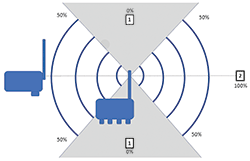
Consider the following when planning a wireless network. (See Figure 1):
• No signal will be radiated directly above and below the antenna (1).
• Most signal power is in the horizontal plane (2).
Other considerations regarding antenna positioning:
• Keep in mind that outdoor antenna installations have to be safe against lightning strikes. Therefore, install a surge arrestor, to protect the installation against transients or damage caused by lightning strikes.
• If the gateway is located inside a building or in an electrical cabinet, one can use omnidirectional or directional remote antennas. Remember to consider local regulation when installing remote antennas.
• If external antennas are used with the gateway, a high-quality antenna cable has to be used to avoid signal attenuation. The maximum cable length is 18 metres when used with an omni-directional dipole antenna.
Wireless distances
A signal range is defined within four categories:
• Clear line of sight: the antennas are mounted 3 m above the surface and no obstacles are within the Fresnel zone.
• Light infrastructure: this is similar to the case clear line of sight, but with some smaller obstacles in the Fresnel zone.
• Medium infrastructure: some pipes, tanks and infrastructure.
• Heavy infrastructure: many pipes, tanks and vessels in the signal path.
The clear line of sight of radio waves at 2,4 GHz is not a straight line, it is actually an ellipsoid, called the Fresnel zone. This zone has to be free of obstacles to guarantee the best signal strength. Obstacles in this area have an influence on the signal strength.
Currently there are limited tools to assist with the calculation and validation of these wireless distances. There are tools that can calculate a wireless distance, but only on the horizontal plane and cannot determine if there are obstacles in the Fresnel zone.
DesSoft has developed a 3D software tool to assist the engineer in the validation of the wireless ranges and obstacles in the Fresnel zone. (See Figure 2). In this Figure one can clearly see that the tanks are obstacles and that the signals are blocked, therefore some devices cannot serve as repeaters or may not have a range to the gateway.
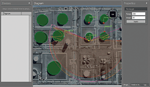
The 3D environment allows users to define the position of the devices as well as the height of the obstacles, tanks in this scenario. Further, it is using a Google Earth image to assist with the distance measurements on the site.
When wireless distances can be accurately validated, installation of the wireless devices can be done more accurately and commissioning can be done quicker and with less ‘experimentation’ of devices and repeaters in the field.
For more information contact Johan Hamman, DesSoft, +27 (0)12 644 2974, [email protected], www.dessoft.co.za
| Tel: | +27 12 644 2974 |
| Email: | [email protected] |
| www: | www.dessoft.tech |
| Articles: | More information and articles about DesSoft |


© Technews Publishing (Pty) Ltd | All Rights Reserved
 printer friendly version