

Safety engineers throughout the world are struggling with the problem of how to best comply with new and more stringent safety requirements.
IEC requirements state that manufacturers must determine and document precise levels of safety and furnish quantifiable proof of compliance. In light of these requirements, manufacturing companies feel it is necessary to reassess their traditional safety loop testing procedures. In particular, they feel it is important to improve their safety valve testing procedures in order to drive costs down and improve plant safety.
Background
Potential disasters at an industrial processing plant may include an accident resulting in a massive release of toxic materials, an uncontrollable re, a devastating explosion or any combination of the above. Some industries are more prone to one over another of these catastrophes, but every company must guard against all potential disaster scenarios.
Perhaps this is why some manufacturers have taken a proactive stance, becoming early implementers of the safety standards. Such standards include IEC 61508 (Functional Safety of Electric, Electronic and Programmable Electronic Systems) - which is a general standard that covers functional safety related to all kinds of processing and manufacturing plants. IEC 61511 is a subset of the general standard specific to the process industries. Also ISA SP84 committee has released a new standard, which builds on the abovementioned international standard. No matter how far along manufacturers are in SIS development, a primary concern of each is adopting a reliable and effective method for ascertaining, monitoring and maintaining the integrity of critical emergency shutdown and venting valves.
Valve availability is critical to safety loop performance
In recent years it has become increasingly apparent that the total reliability of any safety loop is heavily dependent on the availability and reliability of its final elements. When overall loop performance, from system to final element, is quantified, it is easy to see that the weak link of most safety loops is the potential non-operability of safety valves, since they alone account for roughly one half of the probability of a dangerous failure (see Figure 1). [OREDA - Offshore Reliability Data book]
Emergency shutdown and venting valves are the final line of defence and are critical to minimising the chance of fire or explosion during process upsets. As these emergency valves are rarely cycled, however, there is always concern over whether they will operate if actually needed. In fact, if these valves are not periodically stroked, it can almost be guaranteed that they will not work when called upon.
Although their importance to safety loops has often been overlooked in the past, IEC standards are forcing instrumentation technicians to significantly increase the frequency of their safety valve testing procedures. In order to meet and maintain desired SIL requirements, it has become necessary for manufacturers to test many of their safety valves several times a year. Faced with these increased valve testing requirements, manufacturers realise they must improve their conventional safety valve testing methods to avoid significant recurring labour costs.
Theory behind the valve testing
It has been known that testing of emergency valves improve the availability and on some level detects the fully non-functional valves. Many operators are simply afraid to physically move the valve. Due to long passive period the valves may do unexpected operations and thus cause an emergency situation or a nuisance trip. Somebody may even ask, if it is safer NOT to test the valves? The answer is NO. Correct testing methods and testing intervals must be chosen.
This concern can be clearly expressed as a simple question: How sure can I be that my safety valves will actually work when they are called upon in emergency? Fortunately, some companies can be confident that their safety valves will work if they understand and optimise all of the variables in one very important equation.
The IEC 61508 standard requires manufacturers to evaluate every area of their plant, assigning a safety integrity level (SIL) to each area based on the severity of damage that might occur during the 'worst case' accident. SIL levels range from 1 to 4. The higher the SIL, the more demanding the availability requirement for the safety loop.
*Low demand mode: Frequency of demands no greater than once per year and no greater than twice the proof check frequency. The statistical measure of availability in an emergency is called the probability of failure on demand (PFD) and may be obtained by solving the following equation:
PFD = DC • λd • TIA + (1 - DC) • λd • TIM
Where:
DC = diagnostic coverage factor.
λd = dangerous failure rate = 1/MTBF (mean time between dangerous failures).
TIA = testing interval for automatic tests (on-line tests).
TIM = testing interval for manual tests (off-line tests).
For the individual component (eg, valve) the PFD1oo1 (one out of one) can be calculated from the following similar equation:
where additionally:
MTTR = mean time to repair.
Availability is the issue
In an ideal word, the probability that a safety valve will not perform its intended function when called upon would be zero. For critical safety valves in this imperfect world, the PFD number should be as close to zero as possible. Enough work has been done to know that PFD can be reduced to near zero level by ensuring that each expression in this equation is represented by the best possible value.
Unfortunately, the certainty that even the best safety valve packages will be available when needed diminishes over time. Equipment deterioration or damage, no matter how unlikely, can always occur. The only way to minimise the uncertainty is to frequently inspect and test the safety equipment, and most importantly the safety valve. As seen in 4/10 Figure 1, safety valves account for roughly one half of the probability of dangerous failures in safety loop.
This can be seen also in the IEC 61508 guideline for allocating the probability of a failure on demand between the different components in the safety loop (see Figure 2).
The fact that 50% should be allocated to final element shows that they are the biggest reliability problem in safety loops. This is also easy to understand since they are moving mechanical devices operating in a very demanding environment, and like cars, they require periodic maintenance to stay operational.
Random manual tests, however, are not the answer. It is well known that random tests on valves that frequently remain in one position for long periods of time may present a risk. A clogged valve may suddenly exceed the chosen test stroke length, thereby causing danger to a process or an unwanted process shutdown.
Frequent automated partial stroke testing of the valves while the plant is running and conducting full stroke tests during shutdowns is the most effective way to test the integrity of your safety system. Partial stroke testing allows extending the shutdown interval and thus allows longer uptime for the process.
Human error can lead to serious consequences. Conventional testing provides very little information about valve performance. Such tests may only provide information about visible movement and does not confirm whether or not the required operating safety margin is available. For example, the breakaway torque could be so high that the actuator cannot execute the next stroke, leading to a dangerous valve non-operability or possible process shutdown. Therefore, for safety's sake, and for substantial cost savings, online monitoring, testing and data collection is the most reliable way to prove valve functionality.
Automatic partial stroke testing increases diagnostics coverage
The extent to which a given testing and monitoring approach indicates everything that could possibly cause a valve to fail (expressed as a percentage) is called the diagnostic coverage (DC). A manual partial stroke test using a jamming device momentarily improves diagnostic coverage by confirming that the valve is working at that specific moment. This type of testing also poses safety risks due to the possibility of human error at the test site and because the valve is temporarily inoperable during the test.
Partial stroke tests, on the other hand, can be initiated remotely and data can be collected, providing a fingerprint of the valve's condition. Over time, technicians can compare these fingerprints and evaluate if a serious trend toward performance degradation is developing. The effectiveness of this approach depends on the skills of the evaluator and the frequency of the testing. This can be a tedious task, particularly if there are dozens of critical safety valves. There is also another option for evaluating valve performance degradation, history trends.
Very good online diagnostic coverage numbers have been derived from a patented safety valve monitoring and testing system, Metso Automation's Neles ValvGuard. It automatically initiates device self-checks and partial stroke tests for the emergency valve package, collects data, and generates trends that indicate when the device will need servicing in order to maintain a wide margin of error. For this system diagnostic coverage is 75% for normally open emergency shutdown valves and 95% for normally closed venting valves. When automated acoustic leakage measurement system is added into the Neles ValvGuard system for emergency venting valves, the diagnostics coverage approaches 100%.
MTBF representing the device field reliability
The mean time between failures (MTBF) is a numerical average representing the device field reliability in number of years. The sum of several identical valve packages multiplied by number of failure free operating months will give the MTBF. This is not the single valve's lifetime but a well-recorded performance of several valves under agreed process conditions. Obviously, the higher the safety valve package's (including the partial stroke testing system) MTBF, the lower the PFD.
The most reliable MTBF data is based on field experience, involving actual safety valve packages. In order for MTBF data to be statistically significant, however, a considerable number of units must be in use for many years. Since there is a very small installed base of valve packages statistically monitored and registered in safety instrumented systems, most MTBF data currently available is based on laboratory testing as well as calculations involving theoretically comparable data or generic data provided by trusted industry sources. Plant operators should jointly with equipment manufacturers review the installed emergency valves' performance and create the plant specific data of the valves' performance. Eg, Neles D1 series metal and soft-seated ball valves show excellent field performance, the MTBF equals 240 operational years.
The closer the data approximates actual usage, the better. For example, the electronics used in the Neles ValvGuard system are based on Metso Automation's ND800 digital valve controller technology, which has grown to an installed base of a hundred thousand units over the past decade, with almost no PCB failures. Therefore, it is reasonable to conclude that the MTBF for Neles ValvGuard system's onboard electronics would be of the same high magnitude. Also the onboard electronics do not affect the safety function of the device.
The calculated MTBF for a given valve package is considered to be the sum of MTBF numbers of each individual component. If a manufacturer cannot supply the MTBF for one of its components, then the value used in the calculation will be zero. In the absence of field data, more credibility is given to MTBF calculations, which take into account laboratory testing of fully assembled packages (eg, valves and actuators) as opposed to individual components that are tested separately.
Repairing time may become critical
The PFD equation of a component also takes into account MTTR (mean time to repair), which indicates how long it generally takes to fix a problem once it has been identified. Unless there is redundant protection, this value represents a period of extreme vulnerability. It should be as low as possible. Commonly used number for emergency shutdown devices is eight hours.
Frequent testing increases integrity level
The longer the time interval between critical safety valve package tests, the less is known about its integrity. So, frequent partial-stroke testing may substantially lower PFD numbers. With manual online testing of critical safety valves, it is rarely possible to test more than once or twice a year. There are, simply, too many critical valves and too few qualified technicians in most plants to do the job. Initiating remote manual testing simplifies the logistics, but still may be limited by the availability of manpower to conduct the test and analyse the data.
Automated online testing and monitoring of automatically collected trend data allows the testing frequency to be as high as desired. While it is certainly possible to perform automated tests many times a day, most plants adequately test safety valves periodically ranging from once a week to once a month. This can already be sufficient to maintain the desired SIL level.
Since partial stroke testing cannot provide 100% diagnostic coverage, full stroke tests also should be conducted during plant shutdowns. More frequent full stroke offline tests improve the overall PFD.
Neles ValvGuard concept
Metso Automation's Neles ValvGuard testing and monitoring system for emergency valve applications is a new generation safety management system that helps ensure that emergency shutdown (ESD) and emergency venting (ESV) valves will operate properly despite long periods of idle service. Unlike traditional safety systems that require testing while the process is completely shut down, with Neles ValvGuard the valve performance is tested and monitored automatically on a continuous, realtime basis, without disturbing the process. Depending upon the specific process needs and the potential for danger, an online testing sequence can be defined from many times a day up to once a year. ValvGuard is also one of the few smart partial stroke test devices certified by TÜV up to SIL3.
The system automatically monitors safety valve performance trends (see Figure 3) and provides a warning so that simple low-cost actions can be implemented before a dangerous situation occurs. Because the exact condition of the valve is known at all times, maintenance periods can be extended and unnecessary process shutdowns and repairs avoided.
The Neles ValvGuard System consists of three components: VG800 field device, RCI Remote Control Interface and Metso Automation FieldCare condition monitoring and configuration software.
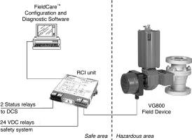
VG800 is used in the field in the hazardous areas together with a pneumatic actuator and an emergency shutdown valve. It has a microcontroller and onboard memory to perform partial stroke tests and collect diagnostics information. ValvGuard also includes internal pneumatics, ie, solenoid valve, which is used to perform the safety function. Thus no additional wiring is needed; Neles ValvGuard is true 2-wire system. The spool valve can be programmed to perform a functional pneumatics test periodically, which is very important for the safety point of view. It has been estimated that solenoid valves cause about 30% of all the final element failures (OREDA). Also, the safety function of Neles ValvGuard is based only on the binary signal from the safety system and not dependent on the onboard electronics. If an emergency signal occurs during testing, ValvGuard automatically bypasses the test procedure and performs the desired safety function.
Because Neles ValvGuard is a smart processor controlled device, monitoring and testing procedures are not dependent upon operator interaction. This minimises any consequences that might have occurred due to human error while, at the same time, dramatically increasing the reliability of the safety system.
Remote Communication Interface is located in the safe area, normally in the cross-connection room. RCI is connected between the safety system and the field device. Its function is to provide HART communication for the configuration and condition monitoring software as well as the status information to DSC. RCI includes two HART independent status relays, which can be hardwired to the DCS to provide the status information of the VG800. Also, three LEDs (green, orange, red) are located in the RCI to show the OK, testing or alarm status.
Metso Automation FieldCare is used for configuration and condition monitoring of the VG800 field device. Data collected during testing is automatically posted to a database, which can be accessed by authorised personnel. FieldCare reduces the cost of compiling mandatory compliance data, makes data accessible for preventive maintenance and provides expanded warning capabilities via digital phone or the Internet.
FieldCare is based on FDT/D technology, the open standard independent of device or system supplier. Field Device Tool (FDT) is a standardised interface specification that allows the integration of intelligent devices into, for example, asset management and process control systems. All configuration and communication information is carried in device type management (D) software supplied by the vendor. Ds run under the control of an FDT frame application.
There are several additional options for Neles ValvGuard system; the leakage detection is one of them. It is applicable for valve configuration where the valve is closed in normal operation; ie, the safety action opens the valve. The ValvGuard constantly monitors the leakage sensor signal and stores measurement data into its onboard memory. The collected data can be viewed as a trend. Leakage signal is shown in mV as function of operation hours.
The sensor is placed on valve body, proximity to a valve seat. This gives the best leakage detection sensitivity. Leakage detection performance depends on several factors including sensor placement, valve configuration, process environment, flow media, pressure level, background noise etc. The minimum detectable leakage order of magnitude is some litres per minute, at its best around 1 litre/minute. This sensing level is adequate to locate damaged valves that require maintenance actions. The flow (or leakage) inside a valve must be turbulent in order to emit high frequency noise and thus be detectable by the transducer.
Conclusions
The potential of a non-operating field device is still a big problem in most safety systems, since the final elements, often valves, account for roughly half of the probability of dangerous failures. The only way to ensure the valve's availability is to frequently test the system. But, closing the valves completely, in most cases, is not a feasible solution. That is why online partial stroke testing, with additional diagnostics, is increasingly more important.
Automating the partial stroke testing routine using intelligent emergency valve technology will help to increase safety with more frequent testing and also optimise maintenance of the final elements with the additional diagnostics data received. At the same time automated testing will decrease the costs associated with manual online testing. The most important feature of these intelligent automated testing systems is that, for the first time, good quality feedback from the final control element is available to operators and maintenance personnel, to truly minimise the probability of failure on demand.
For more information contact Metso, 031 502 9350.
| Tel: | +27 31 502 9350 |
| Email: | [email protected] |
| www: | www.valmet.com/flowcontrol/ |
| Articles: | More information and articles about Valmet South Africa, Flow Control |


© Technews Publishing (Pty) Ltd | All Rights Reserved
 printer friendly version