

I was recently asked to conduct a control loop audit on a mineral extraction processing plant which was fairly old and had been acquired by new owners. A new and very modern control system had been installed on the plant, but with the exception of some of the measuring transmitters, the other control components such as valves and variable speed pumps were the originals.
The plant had been running for some time after the new owners had taken over, and the recoveries were not as good as had been hoped. The plant process engineers were of the opinion that the problem was mainly due to poor tuning of the controllers, and this was the reason why they contracted me to conduct the audit.
Once I started work in the plant I soon established that whilst the tuning on the whole was not as good as it could be, the main problems were due to really bad and vastly oversized valves and pumps.
It is sometimes extremely difficult to explain to process engineers who have had no practical control training that tuning will not solve all problems. Many of them seem to believe that if there is a controller installed on a process, then it can control anything, and all that needs to be done is put in the correct tuning parameters. I have listed below some basic points on practical control which is directed more at controls on mineral processing plants.
General discussion on practical control and its limitations
1. Feedback control systems can do a remarkable job, but do have limitations insomuch as they can only operate at a maximum speed, which is limited by the dynamics of the process. As a general rule, fast processes like flows can be controlled quickly. Slow processes can only be controlled slowly. This particularly applies to many levels and things like temperature and pH. In addition, good feedback control is completely reliant on good loop components, like the measuring transmitter and particularly the final control element like control valves and VSPs (variable speed pumps). In addition, feedback control cannot have zero variance (i.e. eliminate all errors), as the control can only act after an error occurs. (Error is defined as the difference between the measured process variable and the setpoint.)
2. Control problems: it is often not realised by non-control personnel that tuning is mostly not the problem. The vast majority of control problems are caused by problems in the other loop components, which include the measuring transmitter, the valve and the actual process itself.
3. 90% of all control problems are caused by the final control element. Its function is to ‘translate’ the demands of the controller into a physical input to the process. The final control element must ‘follow’ the controller’s output exactly. The better and faster the final control element operates, the better will be the control. The control element must also be also sized correctly. Oversized control elements multiply all their problems by the oversize factor. In particular valve sizing is not based on line size. Properly sized control valves are generally one or two sizes smaller than the line size. Good control valves are expensive, but allow much better control than cheaper alternatives. It should be noted that as a general rule of thumb, control valves should ideally operate above 20% of opening. Also, trying to control when the valve is below 10% of opening should be avoided at all costs. For a variety of reasons, valves can have problems trying to control so near the seat. If a valve is operating very low down at normal plant loads, it is generally a sign of extreme oversize.
Another point in metallurgical plants pumping slurries is that valves operating very low down frequently clog. This then causes the controller to try and open them until the blockage clears, which then causes a big surge in the flow through the valve that ‘hits’ downstream processes.
4. Variable speed centrifugal pumps have a problem insomuch that they cannot operate below a minimum speed, which is often around 30 – 40%. This can limit the range of control, and it makes pump sizing very important for control. For example, in one particular case I encountered recently I found a pump stopping at 60%. The operating speed at the current load was actually only a few percent higher.
5. Cascade control: it is excellent practice to employ this technique with important slow processes, such as levels and temperatures. Slow processes can only be controlled relatively slowly, and it is vital that the final control elements do exactly what the ‘master’ controller demands. Therefore if one feeds the output of this master controller to the setpoint of a ‘slave’ flow controller, which controls the final control element, then one can often get away with all sorts of valve or pump problems, as the flow control loop is extremely fast and will at least get the final element to deliver the correct flow relatively quickly. Even if the flow loop is in a complete cycle, which is occurring on at least one of the loops on the plant I was in, it will allow the master to keep its PV well at setpoint.
6. It must also be realised that process dynamics can change with time, as components wear or tanks get ‘build-up’, and may be quite different at different loads. Therefore tuning must be revisited from time to time.
The most common problems I encounter in metallurgical plants are as follows:
• Oversized valves and pumps.
• Unsuitable valves: however it must be noted that on slurry applications there are only a few valve types that can be used. The most commonly used valve these days is the Dart valve.
• For some reason the airflow valves in nearly every plant I have been in are really bad and very sticky. People are not normally aware of this as they generally don’t change the airflows very often.
• Cheap measuring equipment.
• Poor control strategies, like undersized sumps: these vessels very often perform an important function by ‘buffering’ surges caused by varying inputs to the sumps, and thus allow a relatively constant flow of product to downstream processing units. The actual level in the sump is generally not important, provided it does not go too high or too low. Unfortunately personnel with little understanding of the control objectives often tune the level controllers on the sumps with fast parameters to try and keep the level constant – sometimes referred to as ‘tight level control’.
• Because of the limitations of speed at which feedback control can react, the control will operate much better if feeds to processes can be kept as constant as possible, and if they do vary, then the changes into downstream processes should be as slow as possible to allow controls to catch the changes. Therefore upstream buffering (surge tanks) helps stabilise processes like float banks.
• A control system does not eliminate variance; it merely transfers it from one side of the process to the other. For example if we have varying input to a float cell and we control the level, then keeping the level constant will transfer the variance to the input of the next cell. Unfortunately level controllers in most float cells can only be tuned relatively slowly, so they cannot deal effectively with rapidly fluctuating inputs, and the fluctuations will increase as you go down the bank. The only methods to overcome this are firstly to keep the input to the bank as constant as possible, typically by using a surge tank that will absorb input fluctuations, or secondly, by the use of more advanced control feedforward/feedback combination systems. There are several of these commercially available, but they do need to be tuned properly and the tuning checked at regular intervals as plant conditions change with time.
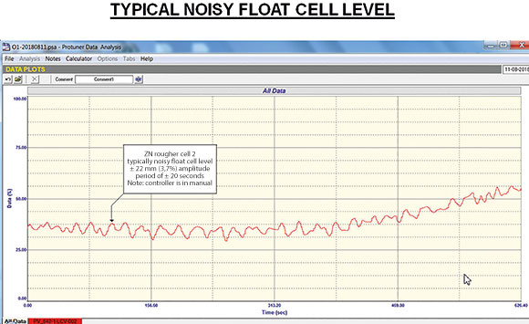
• Random fluctuations in measurement usually occurring at relatively high frequencies are referred to by control people as ‘noise’ (see Figure 1). This is often mistaken by plant personnel as bad control and instability. However, the noise frequencies are usually far too high to really have any effect on the process, and in fact in most cases do not actually interfere with the control.
Modern control systems can easily hide the noise on the process variable if you insert filtering (damping) on the signal coming in from the process. It makes the trends much smoother and they look much better. However, there are two major drawbacks to this: firstly what you see on the screen is not what is actually happening in the process, and sometimes with huge filters you do not see things like surges or other problems. Secondly, the filter forces you to slow the tuning down to deal with this extra lag in the dynamics, and your control response can be seriously affected.
Unfortunately, as it is easy with modern digital control systems to implement filters of any magnitude, they are often applied.
Plant personnel then become accustomed to seeing smooth lines on trends, and everything looks much better. When I remove filters, the operators mistake the noise for instability and get very upset. However, they need to be trained on the problems with filters.
The one problem that can occur with noise is that it passes through the controller, and if the controller’s gain is relatively high it can possibly bump the valve around, which can shorten its life. Furthermore, the flow through the valve also starts jumping around, and passes this into the next process. Therefore, in the case of processes like flotation tanks where the one vessel feeds the next down the line, it may be necessary to use filters to try and avoid this happening.
My own philosophy in plants is to try and control without a filter, however horrible it looks on the screen, and if I do use them, then I keep the filter as small as possible.
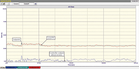
Test for oversized valves
To conclude the article is a test performed on the plant that illustrates an extremely easy way to see if a valve is oversized. Figure 2 shows a closed loop test performed after tuning on a tank level control. The test was performed at normal load conditions and it can be seen that the controller output is working extremely low down, in fact below 5%, which means that the valve is almost at seat. This is not a region where one should even consider controlling, and it is amazing that such good control was being achieved.

Michael Brown is a specialist in control loop optimisation with many years of experience in process control instrumentation. His main activities are consulting, and teaching practical control loop analysis and optimisation. He gives training courses which can be held in clients’ plants, where students can have the added benefit of practising on live loops. His work takes him to plants all over South Africa and also to other countries. He can be contacted at Michael Brown Control Engineering cc, +27 82 440 7790, [email protected], www.controlloop.co.za
| Email: | [email protected] |
| www: | www.controlloop.co.za |
| Articles: | More information and articles about Michael Brown Control Engineering |


© Technews Publishing (Pty) Ltd | All Rights Reserved
 printer friendly version