

It still fascinates me that so many control problems are caused by poor operation of control valves. I have encountered and recorded hundreds of cases of such problems. What is amazing is that many plant people still do not realise that these control problems are valve related, and in most cases, waste a lot of time trying to resolve the problems by playing with the tuning knobs.
This article shows two more examples of controls being completely hampered by the valve performance.
Example 1: Flow control in a refinery
The first example is of a very important flow control in a refinery. The operators were complaining that the loop was not controlling and they even had trouble trying to control it in manual. They wished to control the flow between 25% and 35% of the measuring range. They reported that they had no real problem with the control once the SP was above 32%, but they found they could not get any control below that point.
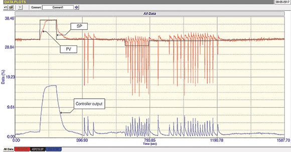
The initial test one always does is with the loop in automatic, without changing any of the tuning parameters or other controller settings. This test is shown in Figure 1. It can be seen that the control initially looked fine and followed a SP step change upwards and back again reasonably well. Then, after a while, the flow started spiking downwards. This was intermittent until the SP was stepped down a few percent and then the spiking became continuous.
The reasons for this can be seen by looking at the values of the PV and the PD (controller output) at the point where the spiking starts. The PV is at approximately 31% and the PD is at 2%. If the valve/positioner combination had been calibrated correctly then it means that the valve is just about shut. Now control valves should never be operated in a control region with their position close to seat. For a variety of reasons valve manufacturers are not able to get valves to operate successfully at very low openings. An old lore of control suggests that for reliable control you should always operate valves above 20% of opening.
Problems with valves operating close to the seat
Two of the main problems with valves operating close to seat are firstly, from the linearity aspect, it is very difficult to get a valve to follow its design characteristics when the valve is really near the seat. And secondly, and probably in this case even more important, many valves when installed in the line have increasing differential pressure as the valve moves towards the closed position. If the actuator is not powerful enough to deal with the differential pressure near seat then cycling commonly occurs, which is probably what we are seeing here, and would support the proposal that the valve is in fact calibrated correctly.
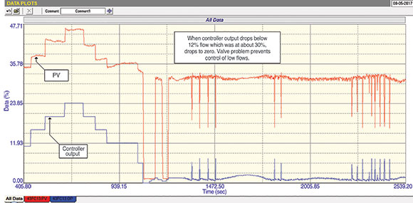
The next thing to consider is why the flow is at 31% when the valve is at 2%. This may be better answered by looking at Figure 2, which is an open loop test performed by placing the controller into manual and removing any filters (damping), if there are any, in both the transmitter and control system, and then making a series of step changes.
The first thing that one should determine is if the transmitter calibration is correct. (Unfortunately in the plant where these tests were being carried out, for several reasons, it was not possible to have an instrument mechanician standing by to answer these questions on the spot, and our reports were passed to their department for the problems to be sorted out as soon as they can manage to do so.) It would, however, appear that there is definitely something wrong with the valve, as the flow does drop to zero when the PD drops below 2%, so it doesn’t appear that the valve is passing. However, the instant the PD rose over 2% the flow jumps straight to around 31%. This is very strange and our recommendation was that the valve should be checked thoroughly, as there may be a problem in the positioner or actuator.
The next thing seen from this open loop test is that there appear to be non-linear installed characteristics, since as the PV steps increased in size as the PD moved up in steps of equal magnitude. Unfortunately we were not allowed to move the flow up past 50% to examine this in more detail, which would also have given us an idea if the valve was sized correctly, and also allow confirmation of the non-linearity. It would appear likely however that the valve is very oversized.
In any event, the tests confirmed that no proper control can be achieved until the problems with the valve, and possibly the measuring system, are resolved.
Example 2: Cacaded level control
The second example of a poor valve is a flow loop that was a cascade secondary to a level control. The level had to be tuned ‘tightly’ to try and keep it on SP as closely as possible under all conditions. The operators had noticed that the flow control was not working well and said they would welcome an improvement in its performance. They stated that the level control itself was still reasonable.
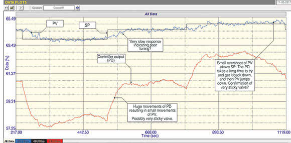
Figure 3 is the ‘as found’ closed loop test, which is similar to the first test described in the previous example. It showed that the PV did follow SP, albeit quite slowly.
Three conclusions drawn from the test results
Firstly, the PD (controller output) moved significantly more than the resultant moves in the PV. There could be two reasons for this. The first is that the process gain of the loop is very small which is usually caused by a transmitter with too wide a span. The second is that the valve is extremely sticky. In view of the fact that the PV readings were above 60% in this case, it is more likely that the valve is sticky.
Secondly, the response of the PV to step changes in SP were quite slow, which is probably due to poor tuning.
Thirdly, one can see that when the PV over or undershoots the SP, it took quite a while for the PD to correct the error. The very last step in the test illustrates this extremely well. The PV moved slightly above the SP. The PD then started ramping down to bring the PV back again, and actually moved several percent before any effect was seen, which was the PV slipping down very quickly under SP. This is a definite sign of a valve with hysteresis and/or stickiness.
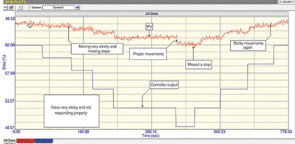
These observations were confirmed by the open loop test shown in Figure 4. It can be seen here very nicely how the valve was very sticky at times, but seemed to move better when closing. However, when stepped in the opening direction it responded extremely slowly. This valve is definitely sticky. (No real evidence of hysteresis can be seen in the results of this test.)
Once again the valve needs work before good control can be obtained. However, it should be noted that if the level did not have the secondary flow loop, and was going directly to the valve, it is very unlikely that any proper level control would have been achieved. Even with such a bad valve, cascade secondary flow control helps to overcome the problems unbelievably well.

Michael Brown is a specialist in control loop optimisation with many years of experience in process control instrumentation. His main activities are consulting, and teaching practical control loop analysis and optimisation. He gives training courses which can be held in clients’ plants, where students can have the added benefit of practising on live loops. His work takes him to plants all over South Africa and also to other countries. He can be contacted at Michael Brown Control Engineering cc, +27 (0)82 440 7790, [email protected], www.controlloop.co.za
| Email: | [email protected] |
| www: | www.controlloop.co.za |
| Articles: | More information and articles about Michael Brown Control Engineering |


© Technews Publishing (Pty) Ltd | All Rights Reserved
 printer friendly version