

People often battle for long periods trying to tune a controller to eliminate problems. As I have often said, one of the biggest fallacies found in plants when it comes to control is that “all problems can be sorted by tuning”. Usually when a problem with a control loop arises, the first thing the process people say to the C&I department is: “Please send someone round to tune the controller. The loop isn’t controlling properly.” I have found many C&I technicians and artisans who will spend hours and in some cases even days playing around with the magic P, I and D knobs, trying to get a tune that works, instead of trying to analyse the problem and find out why the loop is not working.
Putting the loop in manual
Generally if the loop can be controlled in manual, then the tuning ends up working because they tune it terribly slow: I define manual control as infinitely slow tuning. Therefore if you can slow the tuning down sufficiently, the loop will apparently start controlling, provided that the process is stable and changes are not occurring. This results in loops looking great on trends running in automatic, with processes sticking to setpoint as if glued there. Such trends have been called ‘Tram Line Trends’. However, as soon as a change occurs, either in the process, or if the operator makes a setpoint change, then the control cannot catch the change, The operator then usually puts the controller into manual and gets the process back to the setpoint. Once there, he puts the control back in automatic. (Another common fallacy is that if a loop is running in automatic, the tuning is good.)
However, this usually does not work on integrating processes, which are inherently unstable and are also terribly susceptible to cycling. Invariably they cannot be left in manual for long because the slightest change in process input or output will cause it to run away. (Remember integrating processes are balancing processes where you have to ensure that the process input equals the output of the process in order to keep the PV constant.)
A practical example
The example given in this article is of a condensate-pot level, which was always cycling. The pot was very small, and so the level could change very rapidly. (Integrating processes with small retention times are always much more difficult to control than those with long retention times.) This loop presented a huge problem for the operators as they could hardly control it in manual, and obviously they couldn’t have someone devoted to sitting continuously on the panel trying to keep this level within limits, so they had it running very badly in automatic. However, load changes frequently caused the level to reach trip limits. Many attempts had been made to tune it properly, all to no avail.
When I was recently called into the plant, this was the first loop they asked me to check.
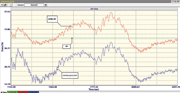
Figure 1 shows the ‘as found’ closed loop test which is conducted with the controller in automatic, with the existing tuning parameters. Normally one performs several setpoint changes to observe response, but in this case it could be seen that the process was moving all over the place so the test shows the performance with a constant setpoint. We then tried to get the process balanced in manual which
is a prerequisite if one wants to do any real analysis and tuning test on an integrating process. However, this proved impossible, with the level jumping up and down and moving around so erratically.
Then, when looking at the P&ID drawings, it was seen that there was an old flowmeter in series with the control valve which had been forgotten about and was never used. That is usually a great thing as one can judge valve performance easily and directly by measuring how the flow through the valve reacts to changes in valve position. I was excited about this but was told that the flowmeter was not working properly and that it was way out of calibration. However, it does not really matter, if the flowmeter is not working perfectly or is inaccurate, when all you want to do is to see how the flow changes when you move the valve. We therefore connected the flow PV to the analyser and performed a valve test. This test is shown in Figure 2, which shows three traces recorded with the level controller in manual:
1. Flow PV.
2. Level PV.
3. Level controller’s output.

One can see that four steps of 5% in the controller’s output were made in the valve opening direction. The test reveals some very interesting information:
On the first steps where the output was being increased, the flow through the valve did not change until the output had moved through 15%, which would indicate the valve was either stuck or subject to large play in linkages (all associated with hysteresis).
When a further 5% step was made in the same direction, the flow increased showing the valve was now moving properly. It can also be seen by looking at the level’s PV trace that the ramp in the level reversed on the last step as the valve had moved past the balance point.
Secondly, when steps were made in the opposite direction, the valve only started moving slightly after the controller’s output had decreased by 10%. This again indicates the same problem. When the controller output was then moved a further 10%, the flow responded quite well, and at the same time the ramp in the level also started reversing, but it should be noted that the controller output was now at zero. The flow PV was at about 50%, but as the calibration of the flowmeter was suspect, this does not mean a lot.
This introduces another possible problem. If the valve has been calibrated correctly to the controller’s output, and the valve was in fact shut (something which we were not able to check at that particular time), and as the process was running around its usual load, then it means that the process balance point is when the controller’s output is close to zero, and the valve is almost shut. This is confirmed by looking at the level reverses on the trend of the level PV, which definitely proves that the balance point is very low down on the output of the level controller.

0This could mean one of two things. Firstly, it could mean that the valve is terribly oversized (which is very probable as the plant has many oversized valves), or secondly, it could mean the seat of the valve is damaged and it is ‘passing.’
Once again, this example shows how important it is to monitor the flow through the valve when controlling integrating processes like levels.
Michael Brown is a specialist in control loop optimisation with many years of experience in process control instrumentation. His main activities are consulting, and teaching practical control loop analysis and optimisation. He gives training courses which can be held in clients’ plants, where students can have the added benefit of practising on live loops. His work takes him to plants all over South Africa and also to other countries. He can be contacted at Michael Brown Control Engineering, +27 (0)82 440 7790, [email protected], www.controlloop.co.za
| Email: | [email protected] |
| www: | www.controlloop.co.za |
| Articles: | More information and articles about Michael Brown Control Engineering |


© Technews Publishing (Pty) Ltd | All Rights Reserved
 printer friendly version