

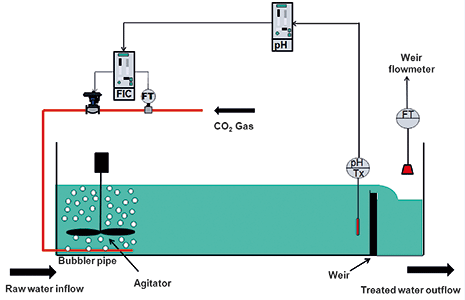
I was recently asked to advise on a bad pH control problem in a water treatment plant. A new carbonisation bay had been installed at the plant: Figure 1 shows the layout of the bay and controls. Raw water is initially treated in an upstream plant where it is desilted and it is then fed in at the one end of the bay. It comes out of that plant and into the bay at a fairly high pH value. Carbon dioxide (CO2) is bubbled though the incoming water to lower the pH to a desired value. The bay is quite long with a large flow of water passing through it. Although there is a high speed agitator at the point where the CO2 is injected to ensure rapid mixing, the pH measuring probe is mounted at the opposite end of the bay to ensure that the chemical reaction has completed and full mixing has occurred. This results in a very long deadtime in the process dynamics which makes control much more difficult as will be discussed later.
The problem being experienced by the plant people was that control was extremely erratic, and was terribly badly affected by load changes in the form of upstream pH changes, and also flow changes through the bay. The latter is the main problem as the plant does run at quite a wide range of throughputs, which are determined by the operators. Once a change of flow is made the control would go unstable or else literally take many, many hours to come back to setpoint.
A non-linear problem on the plant
On arriving at the plant I found that the pH controller was connected directly to the valve and the CO2 flow controller was not in circuit and was unused. However, a flow measurement is extremely useful in analysing the valve performance. Figure 2 is a test showing how the flow through the valve performed versus steps from the output of the pH controller, which was in manual. We were also lucky enough to have a feedback signal of actual valve position, so that is also plotted.
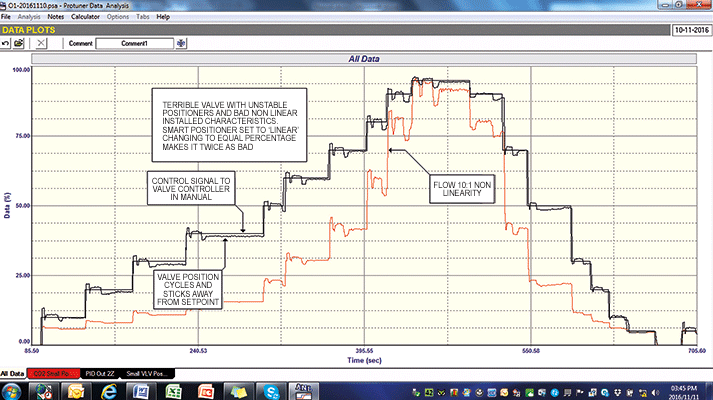
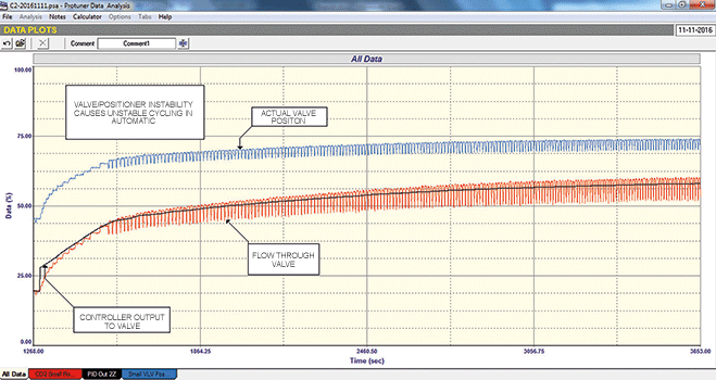
The test showed two faults. The first, which is not terribly serious, is that the positioner/valve combination is almost unstable. This can be clearly seen in the test as there are several cycles of the valve and hence flow after nearly every step change of the controller output. This results in cycling when closed loop flow control is introduced as can be seen in Figure 3. However, although this is not good for the valve it will not really affect the pH control.
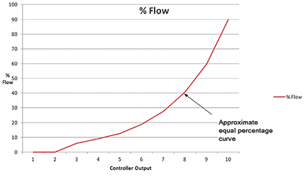
The second and far more serious problem is that the installed valve characteristics are completely non-linear. It can be seen in Figure 2 that the valve is being opened up in steps of 10%. Initially there is no flow until the valve gets up to 10% when the flow jumps immediately to 5%, then with every further 10% step in valve opening the flow increases initially in very small increments which get larger and larger until at near fully open valve position a 10% step change in the valve results in enormous increases in flow. Plotting the flow versus valve travel shows that the valve has an equal percentage installed characteristic. This plot is shown in Figure 4. Effectively the flow versus valve position responses can change by as much as (an enormous) 10:1 over the whole measurement range!
The problem with non-linear installed characteristics is that the control response to a particular set of tuning parameters will vary as one moves though the measuring range, as the process gain is changing.
Why is this serious, particularly in this case?
Firstly, one needs to look at the dynamics of the pH process. Although the tests are not shown here, an open loop analysis of this process at the existing load conditions revealed that they contain a deadtime of about 4 minutes, and two dominant lags of 76 seconds and 23 seconds. This makes for an extremely slow and difficult process as far as feedback control is concerned. Long deadtime in particular is the control engineer’s enemy, and as explained in one of my recent articles (Case History 151), the only way of controlling it with feedback is to slow the control right back to avoid instability. This means that the pH controller has to be tuned really slowly, and this tuning is really critical.
It can now be realised that by connecting the output of the pH controller directly to the valve, it means that if the controller calls for a certain flow of CO2 reagent, it is vitally important that the correct flow does go through the valve. However, with the non-linear installed characteristics of the valve, this can only occur at the one point in the flow measuring range where the tuning was done, and it will be incorrect at all other places.
This is why they were having so much difficulty.
The solution
The obvious solution was to linearise the installed valve characteristics. There are many ways to do this, but the most usual is to make changes in the positioner. Most positioners have various characteristic curves (often called ‘cam curves’) in them to do this, but unfortunately this one did not have a suitable curve for this valve. It was felt in this case that the valve supplier was responsible for supplying the valve with incorrect characteristics, and it was up to them to supply a correct valve.
This would take some time and it was important to get the control working as well as possible in the meantime. One way to overcome the problem is to incorporate a secondary flow control loop to get the flow to the correct value as demanded by the primary pH controller. A properly tuned flow control is extremely fast and operates in a few seconds so if one tunes it to control at the highest process gain, then even when the process gain is very much smaller, and the flow control gets much more sluggish, the flow control will still be able to get the flow to setpoint within a very short time as compared to the response time of the pH process. Thus the non-linearity is completely taken out of the primary pH loop.

I am a great proponent for cascade control when used in the right applications and have had marvellous results with it, as in this case we immediately got good control after the cascade was implemented.
Michael Brown is a specialist in control loop optimisation with many years of experience in process control instrumentation. His main activities are consulting, and teaching practical control loop analysis and optimisation. He gives training courses which can be held in clients’ plants, where students can have the added benefit of practising on live loops. His work takes him to plants all over South Africa and also to other countries. He can be contacted at Michael Brown Control Engineering cc, +27(0)82 440 7790, [email protected], www.controlloop.co.za
| Email: | [email protected] |
| www: | www.controlloop.co.za |
| Articles: | More information and articles about Michael Brown Control Engineering |


© Technews Publishing (Pty) Ltd | All Rights Reserved
 printer friendly version