

Some years ago I gave a talk at a control engineering conference on the control loop problems that exist in process plants and how most people in those plants are unaware that problems exist. A member of the audience, the chief instrument and control engineer of a large chemical plant, told me afterwards that they were using an absolutely fabulous auto tuning package that eliminated all problems and that the controls in their plant were all running beautifully in automatic.
The gentleman moved to another job a few years later and his successor called me in to look at some of the loops, which he did not think were working well at all. Naturally I was very curious to see just how good a job that incredible auto tuning package had done, but what I found was that the controls in the plant were probably amongst the worst I have ever encountered anywhere on that type of plant. The loops were full of problems that had not been recognised. I did not find a single loop that had even close to reasonable tuning, and, although most loops were running in automatic, when the plant was performing at steady state conditions the operators controlled the plant with controllers in manual to change operating set-points or recover from load upsets. The loops were tuned so abysmally slowly that they could not deal adequately with changes.
This article will show a few of the really interesting things I came across during my work in that plant.
Flow loop testing
Figure 1 shows an open loop test on a flow loop that had always been running in manual, even their amazing tuning package had been unable to come up with tuning parameters for this loop.
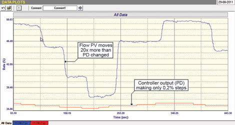
The test shows that the Process Gain is over 20. This is the ratio of the step in PV to the step in PD (controller output) which caused the PV to respond. This ratio for flow loops should ideally be unity. If it is greater than one it usually means the valve is oversized. If less than one it generally means the transmitter span is too wide. In this case a ratio of 20 means the valve is 20 times oversized!
Just looking at the test one can see that a movement of 0,2% on the PD caused the flow to move by close on 5%. This makes control almost impossible as the slightest movement on the controller’s output can jerk the valve around, it is impossible to get fine control. Valves just are not good enough to handle this; they have not got sufficient resolution.
Out of interest, the smallest proportional gain that can be inserted in this client’s DCS system is 0,1 (or 1000% proportional band). When one has high Process Gains in a loop, it is necessary to reduce the proportional gain in the controller. In this particular case the tuning called for a proportional gain of 0,007 (or 14 173% proportional band)! This was one of the most oversized valves I had ever come across.
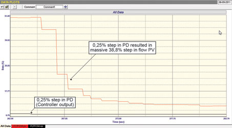
The following day we investigated another flow loop where the operators were complaining that they could not control the flow at all, even in manual. Initial tests gave no real clue as to what was happening; the flow seemed to be doing its own thing irrespective of the value of the PD (controller’s output). A field inspection showed the valve was following the PD reasonably well, although one could see that there was an overshoot on step changes on opening, probably due to poor positioner tuning. We then tried blowing out the impulse lines to the transmitter. This helped a lot and we could see things responding to changes properly, but to our amazement we found the Process Gain of this loop was an unbelievable 150! All records of the previous day were broken. I cannot believe people are trying to control with a valve 150 times oversized – really amazing. A step from the open loop test is illustrated in Figure 2. If it were possible to control with this valve, which of course it is not, then one would need to insert a proportional gain of about 0,003 (or 33 000% proportional band) into the controller. This would make the Guinness Book of World Records.
And now for level
Figure 3 is a closed loop test of a level control loop. This level is in fact uncontrollable, mainly due to an excessively long deadtime. All attempts to try and get the level into balance to allow one to do normal tests in manual so as to determine the process dynamics, and hence to get tuning parameters, failed. Basically the level either ran away upwards or downwards irrespective of whatever one did. The operators did not mind if the loop cycled, their requirement was that the level should not go too high or too low. We determined that if we used a high value of gain using P only control, effectively deliberately increasing the instability, then one could keep the cycle small enough to satisfy the requirements. One should really call it a type of ‘ON/OFF’ control.
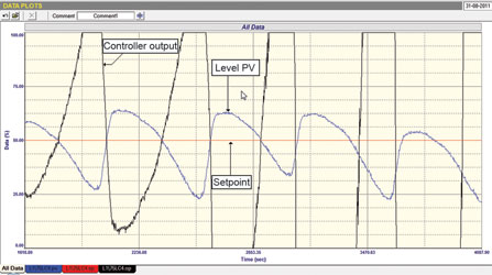
This is not a satisfactory solution, but time did not permit further investigation into why the deadtime was so long and if alternative solutions could be found to achieve better control. However, it certainly worked, even though I cannot say I liked it.
Thumbs down the amazing tuning package
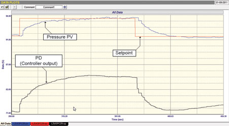
The third and last example in this article is actually of tuning and it shows how poorly the so called amazing tuning package performed in practice. The loop in question is a fuel oil pressure control loop, the secondary cascade to the temperature control of the furnace. The operators were terribly nervous about letting us work on these loops as a huge downstream plant section was dependent on the temperature being held especially constant. Also if the pressure dropped too low, the whole furnace and downstream plant would trip.
Figure 4 shows a closed loop ‘as found’ test using the original tuning parameters: P (gain) = 0,06 and I = 0,05 minutes/repeat.
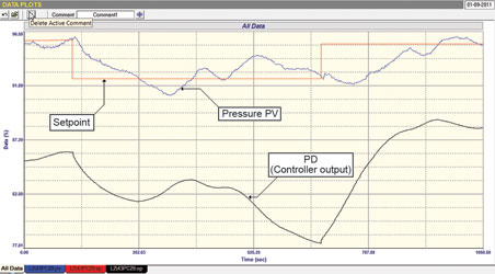
The performance was terrible. The control was virtually never at set-point with the pressure drifting around it all the time. Frequent load changes were also taking place in the oil pressure upstream of the valve and the controller was completely unable to maintain the desired downstream pressure. In the diagram a small set-point change of only 2,5% was made – it took the control nearly 5 minutes to get it close to the new set-point!
Correct, stable and scientific tuning resulted in parameters of: P (gain) = 0,3 and I = 0,03 minutes/repeat.
As can be seen in Figure 5, the response with these parameters to a similar change resulted in the PV reaching set-point in less than a minute. Now, the process can easily deal with the load changes.
It is important to note that it is essential for cascade secondary loops to operate much faster than the primary loop. (Refer Loop Signature Article P1-17 for a detailed discussion on cascade control.) If, as in this example, the secondary is not controlling properly, then there is little chance that the primary loop (which is the important one) will control properly. In this case the primary was the vitally important temperature loop.
More interesting examples taken from the same plant will be given in future articles, including the tuning of the primary temperature loop.

Michael Brown is a specialist in control loop optimisation, with many years of experience in process control instrumentation. His main activities are consulting, and teaching practical control loop analysis and optimisation. He gives training courses which can be held in clients’ plants, where students can have the added benefit of practising on live loops. His work takes him to plants all over South Africa, and also to other countries. He can be contacted at Michael Brown Control Engineering cc, +27(0)11 486 0567, [email protected], www.controlloop.co.za
| Email: | [email protected] |
| www: | www.controlloop.co.za |
| Articles: | More information and articles about Michael Brown Control Engineering |


© Technews Publishing (Pty) Ltd | All Rights Reserved
 printer friendly version